11.3-ADJUSTMENT OF THE CAMBER AND OF THE CASTER
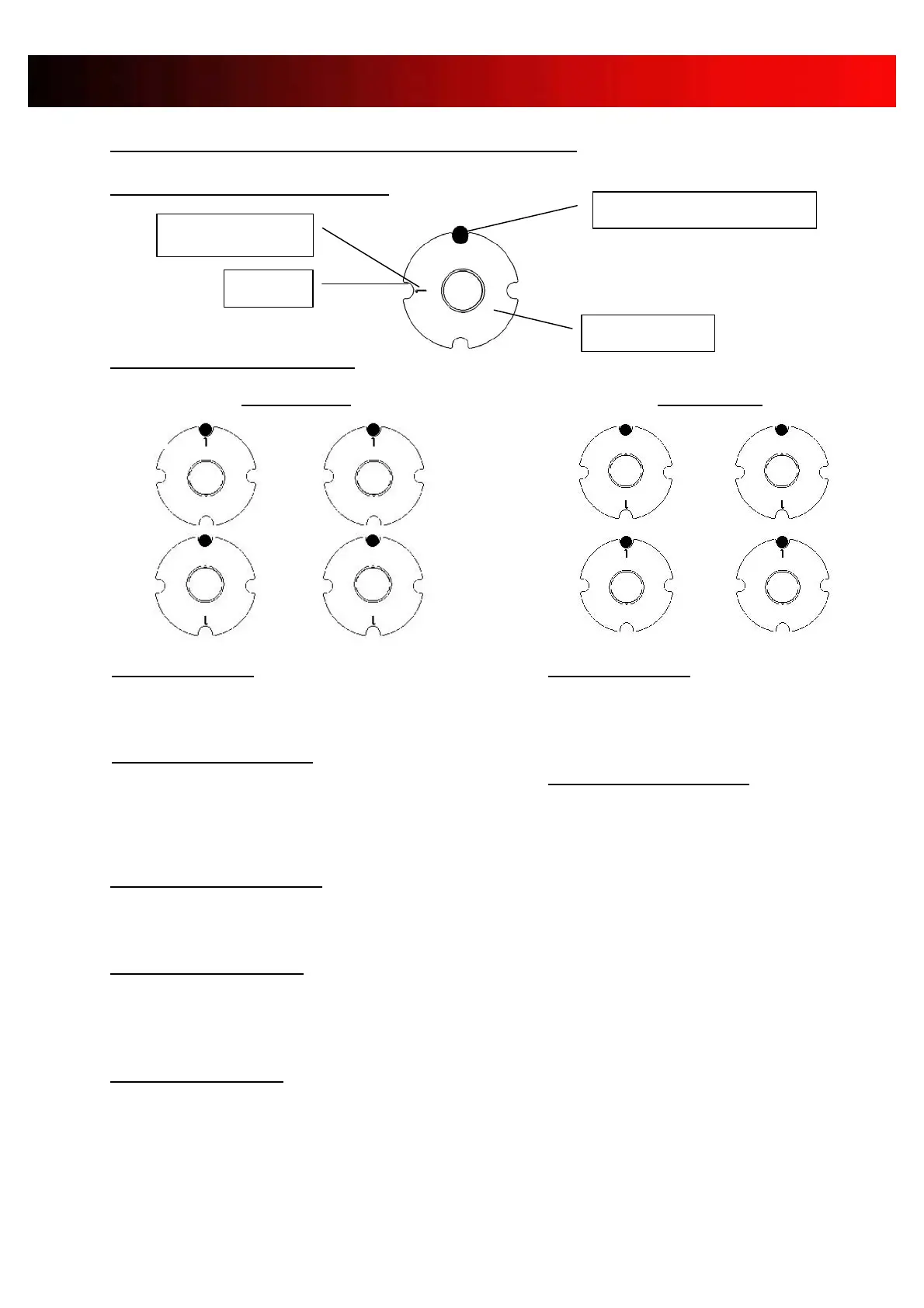
DESCRIPTION OF THE ECCENTRIC.
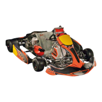
ADJUSTMENT OF THE CASTER
STANDARD ADJUSTMENT (fig 1)
1° eccentrics place in high caster position (fig 1) .
INCREASE THE CASTER (fig 1)
2° eccentric in high caster ( fig 1) position.
In extreme conditions , use 3°!, 4° or more eccentrics.
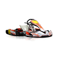
REDUCE THE CASTER (fig 2)
1°ou 2° eccentric ( even more in extreme conditions ) in low caster position .
Eccentrics on top!:
The mark is positioned on the opposite side of
the diam 4 mm pin.
( towards the rear of the chassis ) .
Eccentrics at the bottom!:
The mark is positioned in front of the diam 4 mm
pin (towards the front of the chassis).
Eccentrics on top!:
The mark is positioned in front of the diam 4 mm
pin (towards the front of the chassis).
Eccentrics at the bottom!:
The mark is positioned on the opposite side of
the diam 4 mm pin.
(vers l’arrière du châssis)
diam. 4 mm pin on the fork