34
Connector Assignments and Wiring
10.5 S0
Solar-Log™ devices are equipped with the following S0 interfaces:
•
combined SO_OUT_IN interface (S0-OUT and S0-IN) and
•
S0-IN (only Solar-Log 300, 1200 and 2000)
10.5.1 S0 OUT / IN A (S0-OUT and S0-IN A)
The S0_OUT_IN interface is a hardware interface used for recording measurement values from power
meters and an output for S0 pulses. Use the supplied terminal block connector for the connection to the
Solar-Log™.
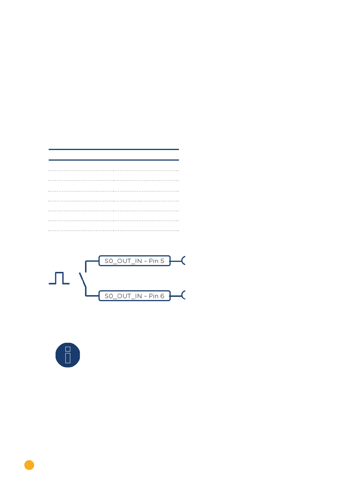
S0_OUT_IN A
PIN Assignment
1 27 mA output
2 27 mA max. input
3 Measuring contact
4 Ground
5 S0 Out+
6 S0 Out-
Fig.: Schematic diagram of the S0 output
Note!
We recommend not using the S0 output for sending current feed amount response sig-
nals to your grid operator.
Due to the internal calculating processes of the Solar-Log™, there would be a delay in
sending the pulses.