Installation Guidelines
For the minimum and maximum number of Power Optimisers in a string (string
length), see the Power Optimiser datasheets. Refer to the Designer for string length
verification. The Designer is available on the SolarEdge website at:
https://www.solaredge.com/products/installer-tools/designer#/.
Do not
use extension cables between a module and a Power Optimiser, between
two modules connected to the same Power Optimiser, or between two Power
Optimisers other than in the following cases:
Between a Power Optimiser and a module:
Extension cables of up to 1.8 m are allowed for all Power Optimisers (0.9 m for
DC+, and 0.9 m for DC -).
P-Series Power Optimisers with the 4-type suffix in their part number (Pxxx-
4xxxxxx) and the Mxxxx-Series - extension cables of up to 16 m can be installed
per Power Optimiser (8 m for DC+, and 8 m for DC-).
Between two Power Optimisers or between a Power Optimiser and the inverter:
Extension cables can be installed between Power Optimisers only from row to
row, around obstacles or pathways within a row and from the end of the string
to the inverter. The total length of the extension cables may not exceed the
following values:
Single Phase Inverters Three Phase Inverters
All - 300 m
SE17K and below - 300 m
SE17.5K and above - 700 m
For connecting homerun DCcables from Power Optimisers to the inverter, use
cables with the following cross-sections:
For MC4 connectors: 2.5-10 mm²
For DCterminal blocks inside the inverter or Connection Unit (if applicable): 2.5-
16 mm²
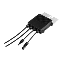
Frame-mounted Power Optimisers are mounted directly on the module frame,
regardless of racking system (rail-less or with rails). For installation of frame-
mounted Power Optimisers, refer to
http://www.solaredge.com/sites/default/files/installing_frame_mounted_power_
optimizers.pdf.
The Power Optimiser can be placed in any orientation.
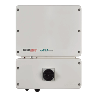
Single Phase Energy Hub Inverter MAN-01-00812-1.1
16 Installation Guidelines
 Loading...