EasyManuals Logo

SolarEdge StorEdge SE10K-RWS Installation Guide

SolarEdge StorEdge SE10K-RWS
71 pages
To Next Page IconTo Next Page
To Previous Page IconTo Previous Page
Page #55 background imageLoading...
Page #55 background image
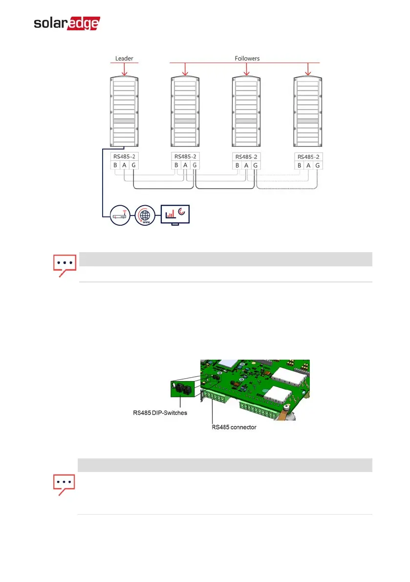
Figure 23: Connecting the inverters in a chain
NOTE
Do not cross-connect B, A and G wires.
6. Tighten the connector screws.
7. Check that the wires are fully inserted and cannot be pulled out easily.
8.
Connect the RS485-2 connector to the RS485 port on the communication board.
9.
Terminate the first and last SolarEdge inverter in the chain. The inverer can be
terminated by switching on (up) the left DIPswitch on the communication board.
Figure 24: RS485 termination switch
NOTE
Only the first and last SolarEdge inverter in the chain must be terminated. In
the other inverters in the chain, the DIPswitch must be in the off (down)
position.
Chapter 7: Setting Up Communication with the Monitoring Platform 54
StorEdge Three Phase Inverter MAN-01-00648-1.3

Table of Contents

Other manuals for SolarEdge StorEdge SE10K-RWS

Questions and Answers:

Question and Answer IconNeed help?

Do you have a question about the SolarEdge StorEdge SE10K-RWS and is the answer not in the manual?

SolarEdge StorEdge SE10K-RWS Specifications

General IconGeneral
TopologyTransformerless
Max Efficiency98.3%
Dimensions540 x 315 x 260 mm
Noise Level< 50 dBA
Protection RatingIP65
Rated AC Power10000 W
AC Frequency50/60 Hz
Maximum Efficiency98.3%
Number of MPP Trackers1
Warranty12 years
AC Output Power10000 W
Operating Temperature Range-25°C to +60°C
AC Voltage230 / 400 Vac
Max Input DC Voltage480 V
Communication InterfacesEthernet, RS485, ZigBee (optional)
Max Charge/Discharge Current25 A
Max Charge/Discharge Power10000 W
CommunicationEthernet, RS485, ZigBee (optional)

Related product manuals