93
05/08
94
en
Block diagram SolarMax 4200S/6000S
7.3 Safety functions
In order to ensure a high safety standard, SolarMax inverters feature integrated fault
current monitoring on the DC side.
In the event of an earth fault current, the fault current monitoring system detects the
differential current and interrupts the mains operation. In the event of accidental con-
tact, the fault current monitoring system triggers a safety mechanism that switches
the device off, thereby preventing electric shock.
7.4 Control functions
SolarMax features state-of-the-art measuring and control electronics. A digital sig-
nal processor (DSP) generates the PWM signals and offers the following inverter
control functions:
n Automatic on/off-switching
n Grid monitoring (overvoltage, undervoltage, mains frequency, detection of
stand-alone operation)
n Mains synchronisation and sinusoidal current control
n Maximum power point tracking (MPPT, searching for the optimum operating
point)
n Output limitation for oversized solar generators
n Input and output current limitation
n Monitoring of the power electronics
n Monitoring of the heat sink temperature
n Control of the graphics display
n External communication via RS485 and/or Ethernet
7 Technical description
A simple and robust design is typical for the SolarMax power unit.
7.1 Technical configuration SolarMax 2000S/3000S
The DC voltage of the solar generator is transferred to a DC bus voltage via a low-
loss step-up converter (DC/DC converter). The IGBT bridge circuit generates the
sinusoidal infeed current.
Block diagram SolarMax 2000S/3000S
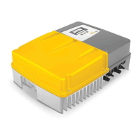
7.2 Technical configuration SolarMax 4200S/6000S
The DC voltage of the solar generator is transferred to a DC bus voltage via a low-
loss step-up converter (DC/DC converter). The IGBT bridge circuit generates the
sinusoidal infeed current.
The innovative MaxShare concept used in the SolarMax 6000C for the first time
leads to a significant increase in efficiency in the partial load range. MaxShare
switches the required power stages on or off according to the current output: