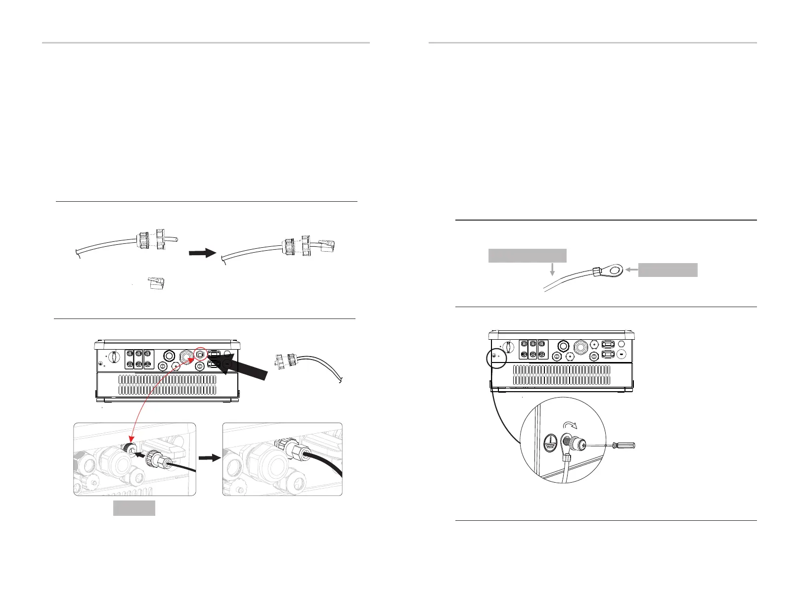
6.5 Earth Connection (mandatory)
Users must addtionally earth the inverter to the enclosure of a second earthing or
equipotential bonding. This prevents electric shock if the original protective
conductor fails.
Earth Connection Steps:
Ø
Step2. Place the ring terminal into the earthing rod and screw the earthing screw
tightly.
Step1. Strip the earthing cable insulation and insert the stripped cable into the
ring terminal, then clamp it .
Cable size: 12AWG.
ring terminal
Step1
Step2
Electrical ConnectionElectrical Connection
32
33
B
C
I
EPS
Grid
+
PV1 P V2 BAT
+ +
- - -
ON
OFF
WiFi
RF
Upgr ade
DRM/Meter
LAN
BMS
CAN/ GEN
Step3
Communication Connection Steps:
Ø
B
C
I
EPS
Grid
+
PV1 P V2 BAT
+ +
- - -
ON
OFF
WiFi
RF
Upgr ade
DRM/Meter
LAN
BMS
CAN/ GEN
Step1
Step3. Insert the cable connector into BMS port inside of inverter and screw it
tightly. Then insert other side of communication cable into RS485 or Can port on
the battery.
Battery BMS module(Pylontech: RS485 port; Triple Power: CAN port; Please check
the battery manual for more details).
Step1. Prepare a communication cable (without sheath) and insert the commu-
nication cable through the cable connector which can be found in the
accessories package .
Step2. Crimp the communication cable with a Rj45 plug which is inside of the
cable connector.
communication cable
cable connector
Rj45 plug
Step2
BMS Port
φ . ± .( 4 hexagon wrench.torque:1 5 0 2Nm)

 Loading...


