6.4 Battery Connection
Charging & discharging system of X1-Hybrid series inverter is designed for
high-voltage lithium battery.
Before choosing battery, please note the maximum voltage of battery can not
exceed 400V and the rated voltage of battery can not exceed 350V, and the
battery communication should be compatible with X1-Hybrid inverter.
Before connecting to battey, please install a nonpolarized DC breaker to make sure
inverter can be securely disconnected during maintanance.
Battery breakerØ
Voltage
Current[A]
32A
Model
X1-Hybrid-3.0-D
X1-Hybrid-3.0-N
X1-Hybrid-3.7-D
X1-Hybrid-3.7-N
X1-Hybrid-4.6-D
X1-Hybrid-4.6-N
X1-Hybrid-5.0-D
X1-Hybrid-5.0-N
Nominal voltage of DC breaker should be larger than maximum
voltage of battery.
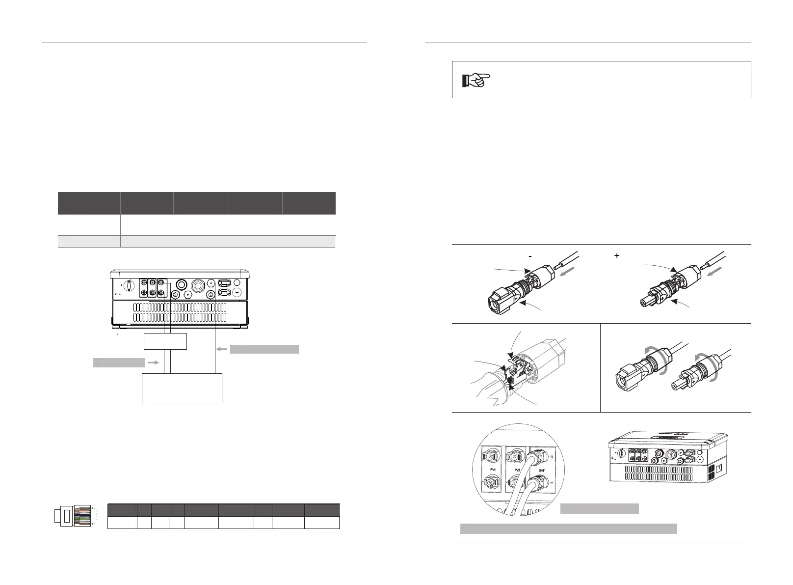
Battery connection diagramØ
Power Connection Steps:
Ø
Step2. Insert the stripped cable up to the stop ( negative cable for DC plug(-) and
positive cable for DC socket(+) are live). Hold the housing on the screw
connection.
Step3 The live wire must be . Press down spring until it clicks audibly into place.(
visible in the chamber)
Step1. Choose the 9 AWG wire and strip the cable to 15mm.
high-voltage lithium battery.
+
-
CAN/RS485
Nonpolarized
DC breaker
Power connection
Communication connection
Communication interface bewteen inverter and battery is CAN with a RJ45
connector.
BMS PIN DefinitionØ
Note!
The battery communication can only work when the battery BMS is
compatible with the inverter.
1
8
DC plug housing(-)
DC socket housing(+)
screw connection
screw connection
spring
chamber
wire strands
Step4. Tighten the screw connection(tighten torque:2.0Nm)
Note: BAT port, not PV port!
Note: The positive line and negative line are not allowed to access anti-Line.
Electrical ConnectionElectrical Connection
Step5. Plug the battery connectors into the corresponding BAT port of inverter.
Step2.
Step3. Step 4.
Step5.
30
31
BMS_CANH
GNDNTC GND
BMS_CANL
Definition
2
3 4
5
6 7 81
PIN
X BMS_485A
Note:
When working with Pylontech batteries, It is recommended the number of battery module
(H48050-15S) is 2-7 and the number of battery manager system (SC0500A-100S) is 1.
When working with SOLAX batteries, It is recommended the number of battery module
(HV10045/HV10063) is 1-3 and the number of battery controller (MC0500) is 1.
BMS_485B
EPS
Grid
+
PV1 PV2 BAT
+ +
- - -
ON
OFF
WiFi
RF
Upgr ade
DRM/Meter
LAN
BMS
CAN/ GEN
EPS
Grid
+
PV1
PV2
BAT
+
+
-
-
-
ON
OFF
Upgra de
DRM/Meter
LAN
BMS
CAN/G EN

 Loading...


