Menu
Grid
Solar
Charger
EPS
Status
History
Setting
System Switch
About
Inverter SN
Register1 SN
Inverter Type
Inverter DSP1
Manager ARM
Internal Code
Date Time
Advanced
Language
Ethernet
need password
On-grid
CT/Meter Setting
Battery
Reset
Safety
Power Factor
Grid
Export Control
Self Test
Charger
EPS
Reset Inv Energy
Reset Meter Energy
Reset Mgr EE
Config Guide
New Password
Reset Errorlog
Inverter Yield
Error Logs
Meter Yield
Work Mode
Relay Control
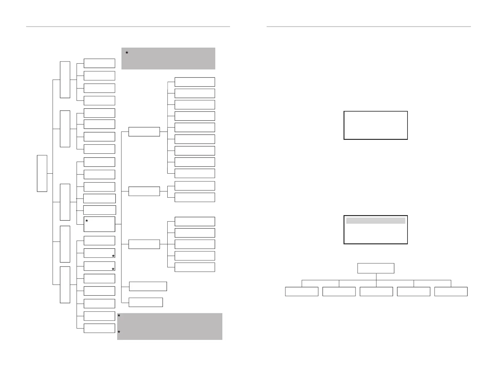
8.2 Menu Structure
All advance setting can only be set
by the technician or the installer with
the installer password.
DRM Function
P(U ) Function
GlblMTTPFunc
Setting Setting
48
49
EPS Yield
Remote Control
SystemRunTime
Register2 SN
Register1 SN: it indicates the serial number of the
external monitoring devices,such as pocket WiFi,
pocket LAN and pocket GPRS.
Register2 SN: it indicates the serial number of built
-in Ethernet.
8.3 LCD Operation
LCD Digital Display
The main interface is the default interface, the inverter will automatically jump to
this interface when the system started up successfully or not operated for a
period of time.
The information of the interface is as below. “Power” means the instant output
power; “Today” means the power generated within the day. “Battery” means the
left capacity of battery energy.
Power 0W
Today 0.0KWh
Battery %
Normal
Status
History
Settings
Menu
Menu interface
The menu interface is a transfer interface for user to get into another interface
to change the setting or getting the information.
-User can get into this interface by pressing “OK” button when LCD displays the
main interface.
-User can select interface by moving the cursor with function button,and press
“OK” to confirm.
Menu
Status
History
Setting
System Switch
About
 Loading...


