Surge protection devices (SPDs) for PV installation
Over-voltage protection with surge arresters should be provided
when the PV power system is installed.
The grid connected inverter is fitted with SPDs in both PV input
side and MAINS side.
WARNING !
Induced surges are the most likely cause of lightning damage in majority or installations,
especially in rural areas where electricity is usually provided by long overhead lines.
Surge may be included on both the PV array conduction and the AC cables
leading to the building.
Specialists in lightning protection should be consulted during the end use application.
Using appropriate external lightning protection, the effect of a direct lightning
strike into a building can be mitigated in a controlled way, and the lightning
current can be discharged into the ground.
Installation of SPDs to protect the inverter against mechanical damage and
excessive stress include a surge arrester in case of a building with external
lightning protection system (LPS) when separation distance is kept.
To protect the DC system, surge suppression device (SPD type2) should be fitted
at the inverter end of the DC cabling and at the array located between the
inverter and the PV generator, if the voltage protection level (VP) of the surge
arresters is greater than 1100V, an additional SPD type 3 required for surge protection
for electrical devices.
To protect the AC system, surge suppression devices (SPD type2) should be
fitted at the main incoming point of AC supply (at the consumer’s cutout),
located between the inverter and the meter/distribution system; SPD (test
impulse D1) for signal line according to EN 61632-1.
All DC cables should be installed to provide as short a run as possible, and positive
and negative cables of the string or main DC supply should be bundled
together. Avoiding the creation of loops in the system. This requirement for
short runs and bundling includes any associated earth bundling conductors.
Spark gap devices are not suitable to be used in DC circuits once conducting,
they won’t stop conducting until the voltage across their terminals is typically
below 30 volts.
Lightning will cause a damage either from a direct strike or from surges due to a
nearby strike.
►
Anti-Islanding Effect
►
Islanding effect is a special phenomenon that grid-connected PV system still
supply power to the nearby grid when the voltage loss is happened in the
power system. It is dangerous for maintenance personnel and the public.
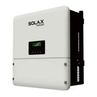
X1-Hybrid seires inverter provide Active Frequency Drift(AFD) to prevent
islanding effect.
PE Connection and Leakage Current
• The end-use application shall monitor the protective conductor by residual
current operated protective device (RCD) with rated fault current Ifn≤240mA
which automatically disconnects the device in case of a fault.
The device is intended to connect to a PV generator with a capacitance limit of
approx 700nf.
High leakage current!
Earth connection essential before connecting supply.
WARNING !
• Incorrect grounding can cause physical injury, death or equipment malfunction
and increase electromagnetic.
• Make sure that grounding conductor is adequately sized as required by safety
regulations.
• Do not connect the ground terminals of the unit in series in case of a multiple
installation. This product can cause current with a d.c component, Where a residual
current operated protective (RCD) or monitoring (RCM) device is used for protection
in case of direct or indirect contact, only an RCD or RCM of type B is allowed
on the supply side of this product.
For United Kingdom
• The installation that connects the equipment to the supply terminals shall
comply with the requirements of BS 7671.
• Electrical installation of PV system shall comply with requirements of BS 7671
and IEC 60364-7-712.
• No protection settings can be altered.
• User shall ensure that equipment is so installed, designed and operated to
maintain at all times compliance with the requirements of ESQCR22(1)(a).
For Australia and New Zealand
• Electrical installation and maintenance shall be conducted by licensed
electrician and shall comply with Australia National Wiring Rules.
►
SafetySafety
06
07
Battery Safety Instructions
►
SolaX X1-Hybrid Series inverter should be worked with high voltage battery, for
the specific parameters such as battery type, nominal voltage and nominal
capacity etc., please refer to section 4.3.
As accumulator batteries may contain potential electric shock and short-circuit
current danger, to avoid accidents that might be thus resulted, the following
warnings should be observed during battery replacement:
1: Do not wear watches, rings or similar metallic items.
2: Use insulated tools.
3: Put on rubber shoes and gloves.
4: Do not place metallic tools and similar metallic parts on the batteries.
5: Switch off load connected to the batteries before dismantling battery
connection terminals.
6: Only personal with proper expertise can carry out the maintenance of
accumulator batteries.

 Loading...