4. Installation4. Installation
.24..23.
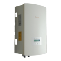
4.7.2.2 Battery Temperature Sensor Connection for Lead-acid Battery
(Optional)
NOTE:
Battery temperature sensor can be optionally used with lead-acid battery for
inverters to accurately detect the battery ambient temperature and adjust
voltage compensation based on the customer-defined coefficient. It is an
optional accessory which may not be provided with the inverter package.
If lead-acid battery is used and battery temperature sensor is needed,
please contact your distributor or Solis sales to purchase individually.
1. Insert the RJ45 terminal end to the CAN port at the bottom of the inverter and fasten
the swivel nut. (Cable length: 1 meter)
2. Fasten the temperature sensor ring onto the battery module. If no suitable fastening
terminal can be found on the battery module, the sensor ring can be attached to the
positive or negative pole of the battery module.
4.7.3.2 Compatible Smart Meter RS485 Connection
Compatible Smart Meter Model
SDM120CT (Default)
Pin 9 – RS485B, Pin 10 – RS485A
Pin 9 – RS485B, Pin 10 – RS485A
Pin 13 – RS485B, Pin 14 – RS485A
B – RS485B, A – RS485A
RJ45 Port on the meter
Pin 7 – RS485B, Pin 8 – RS485A
Pin 21 – RS485A, Pin 22 – RS485B
SDM120M
SDM630MCT
SDM630
ACR10R16DTE
ACR10R16DTE4
Meter RS485 Pin Definition
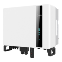
NOTE:
Pin definition of the CAN Port is following
EIA/TIA 568B.
CAN-H on Pin 4: Blue
CAN-L on Pin 5: Blue/White
RJ45terminal
1 2 3 4 5 6 7 8
CAN-H
CAN-L
Figure 4.30
4.7.3 RS485 Meter Port Connection
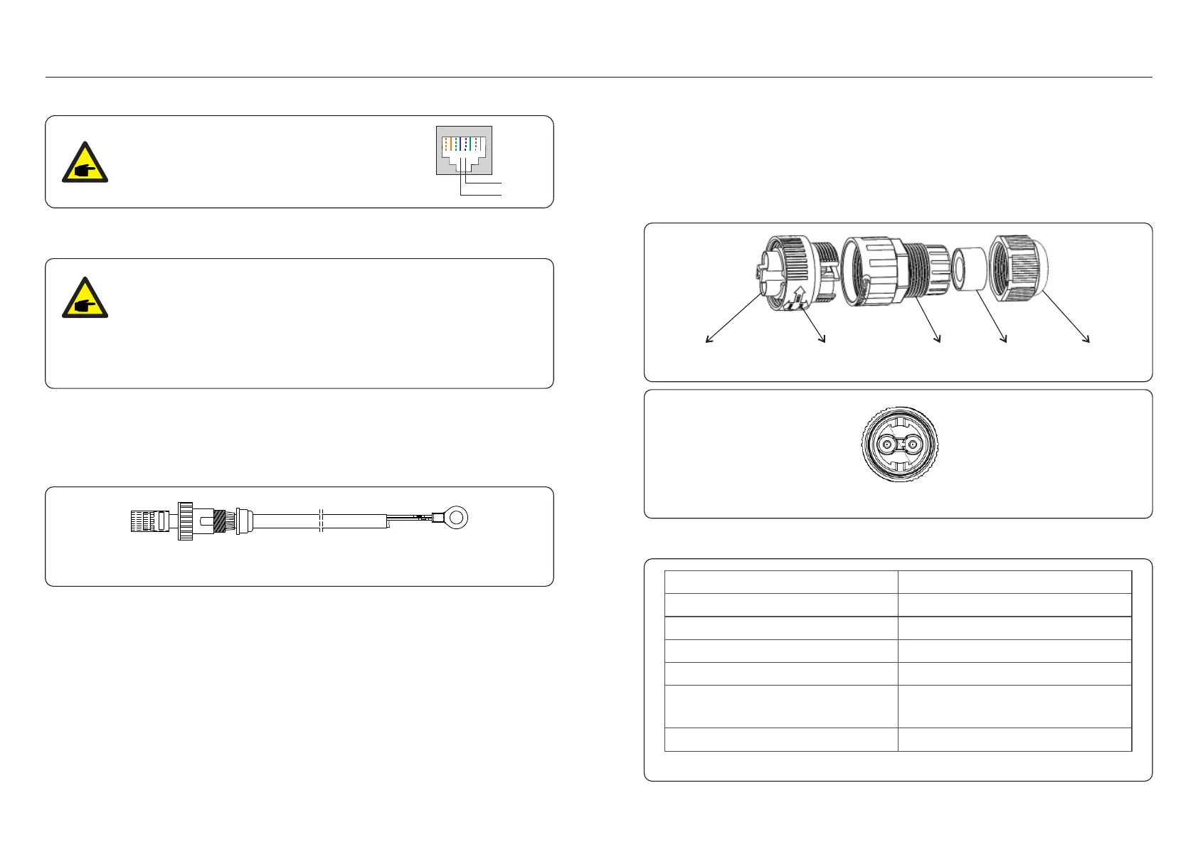
4.7.3.1 RS485 Meter Connector Assemble Steps
A 2-pin connector with 5m RS485 cable for meter communication can be found in the
package. If extending the RS485 cable, please ensure the distance is within 100m and
twisted shielded RS485 cable should be used to prevent signal interference.
Red wire is RS485A
Black wire is RS485B
A. Connection Part
B. Rotatory Ring
C. Main Body D. Sealing Ring
E. Fasten Nut
RS485A RS485B
Figure 4.31
Figure 4.32
Table 4.4

 Loading...