4. Installation4. Installation
4.7.4 DRM Port Connection (Optional)
4.7.4.1 For Remote Shutdown Function
Solis inverters support remote shutdown function to remotely control the inverter
to power on and off through logic signals.
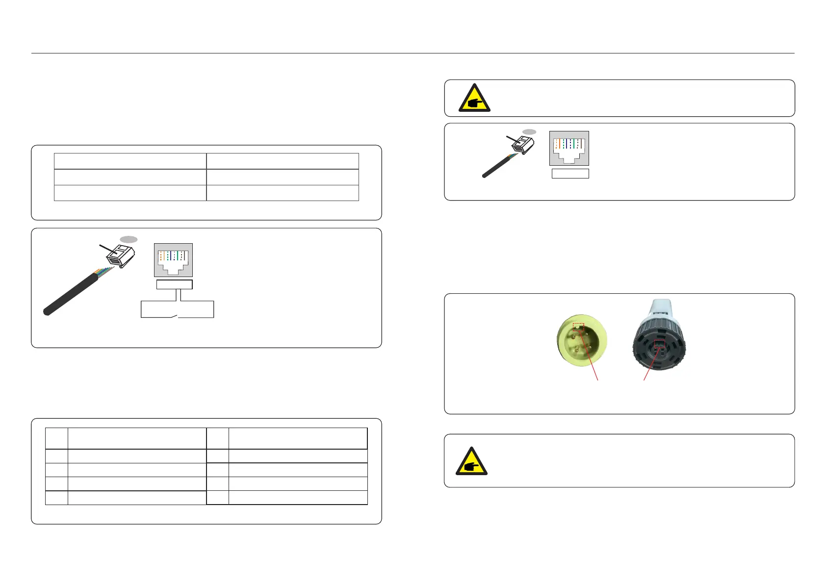
The DRM port is provided with an RJ45 terminal and its Pin5 and Pin6 can be used for
remote shutdown function.
Signal
Short Pin5 and Pin6
Inverter Generates
Inverter Shutdown in 5s
Open Pin5 and Pin6
Function
Correspondence between the cables
and the stitches of plug, Pin5 and Pin6
of RJ45 terminal is used for the logic
interface, other Pins are reserved.
Pin 1: Reserved; Pin 2: Reserved
Pin 3: Reserved; Pin 4: Reserved
Pin 5: Switch_input1; Pin 6: Switch_input2
Pin 7: Reserved; Pin 8: Reserved
1--8
Rj45 plug
RJ45terminal
1 2 3 4 5 6 7 8
1 2 3 4 5 6 7 8
DRM(logic interface)
Switch_input1 Switch_ input2
Figure 4.33 Strip the insulation layer and connect to RJ45 plug
Table 4.5
4.7.5 COM Port Connection (Optional)
COM Port can be used for either Solis Data Logger connection or 3rd party
monitoring/control device with Modbus RTU communication.
4.7.5.1 Solis Data Logger Installation
1. Remove the watertight cap from the COM port.
2. Insert the Solis Data Logger to the COM port to match the joint.
NOTE:
Solis hybrid inverter is designed to provide 12V power for DRED.
Assignment for inverters capable
of both charging and discharging
Pin
1
DRM 1/5
2
DRM 2/6
3
DRM 3/7
4
DRM 4/8
5
RefGen
6
7
8
Com/DRM0
V+
V-
Assignment for inverters capable
of both charging and discharging
Pin
DRED means demand response enable device. The AS/NZS 4777.2 required :2020
inverter need to support demand response mode(DRM).
This function is for inverter that comply with AS/NZS 4777.2 standard.:2020
A RJ45 terminal is used for DRM connection.
4.7.4.2 For DRED Control Function (For AU and NZ Only)
Figure 4.34 Strip the insulation layer and connect to RJ45 plug
Correspondence between the
cables and the stitches of plug
Pin 1: white and orange ; Pin 2: orange
Pin 3: white and green; Pin 4: blue
Pin 5: white and blue; Pin 6: green
Pin 7: white and brown; Pin 8: brown
1--8
RJ45 plug
RJ45terminal
1 2 3 4 5 6 7 8
1 2 3 4 5 6 7 8
Match the joint
Table 4.6
Figure 4.35
.26..25.
3. Rotate the black ring on the Solis Data Logger in clockwise to secure the connection.
NOTE:
Do not rotate the main body of the Solis Data Logger.
It may damage the logger and the inverter COM port.

 Loading...