.19..18.
5. Installation5. Installation
5.3.3 Connect grid side of inverter
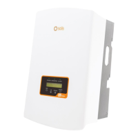
Figure 5.19 AC connector
Internal of AC connector signs "L1","L2","L3","N" and "PE" five connection
ports (see Figure 5.21). Three phase lines shall be connected to the "L1", "L2"
and "L3" terminals respectively, Earth wire shall be connected to "PE" and
Neutral wires shall be connected to "N" terminal.
body
seal body
nut
For all AC connectors, cables with 6mm² diameter are required to be used.
Please make sure the resistance of AC cable is lower than 1.5 ohm.
L2
PE
Outside-diameters
8~18mm
Cross-section
6mm²
18mm
23mm
x
x=7mm
N
L1
L2
L3
Figure 5.20 Stripped and bared wire
Figure 5.21 Internal structure of AC connector
PE
L1
N
L3
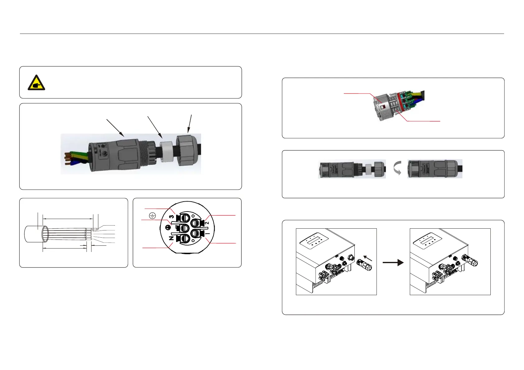
The steps of AC grid terminal connector for installation are as follows:
locker
housing
A) Fix the wires into the correct position and the torque is 0.8N.m
Please try to pull out the wire slightly to make sure that the wires are well connected.
Figure 5.22 Connect Wires to the Terminal
B) Insert the seal and clamp finger into body, then tighten the nut and the torque is 2.5N.m.
Figure 5.23 Tighten up the Cap on the Terminal
C) Connect the AC grid connector to the inverter, until hearing a slight click sound that
indicates the connection succeed.
Figure 5.24 Connect AC connector to inverter

 Loading...