+
-
4.0~6.0
4.0(12AWG)
(12~10AWG)
.17..16.
5. Installation5. Installation
Before connecting inverter, please make sure the PV array open circuit
voltage is within the limit of the inverter.
Before connection, please make sure the polarity of the output voltage of
PV array matches the“DC+”and“DC-”symbols.
Before connecting inverter, please make sure the PV array open circuit
voltage is within the limit of the inverter.
Figure 5.11 DC+ ConnectorFigure 5.12 DC- Connector
Please use approved DC cable for PV system.
Cable type
Cross section(mm²)
Range
Industry generic PV cable
(model:PV1-F)
Recommended value
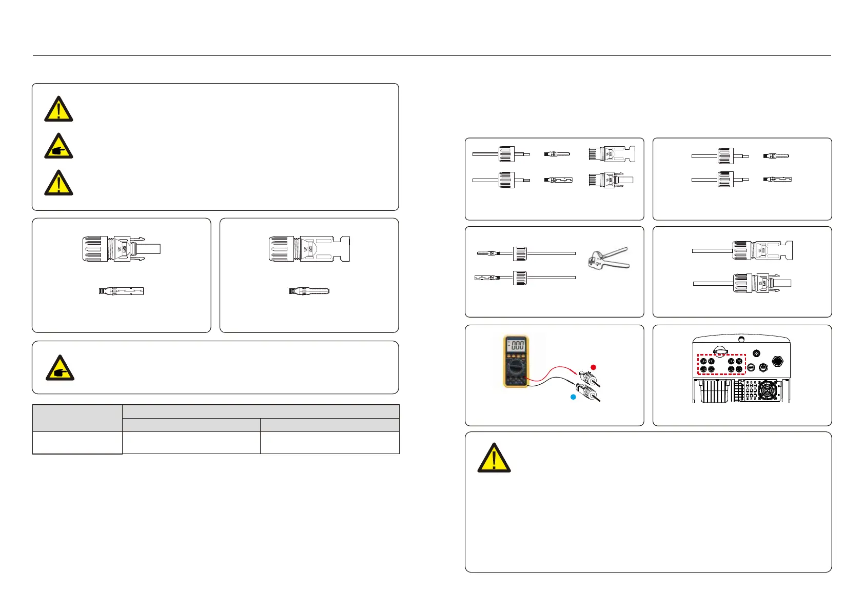
Figure 5.13 Disassemble the Connector Cap nut
Figure 5.14 Insert the Wire into the
Connector Cap nut and contact pin
Figure 5.15 Crimp the contact pin to the wireFigure 5.16 Connector with Cap nut Screwed on
Figure 5.17 Multimeter measurement
Figure 5.18 Connect the DC
Connectors to the Inverter
The steps to assemble the DC connectors are listed as follows:
1. Strip off the DC wire for about 7mm, Disassemble the connector cap nut. (see Figure 5.13)
3. Crimp the contact pin to the wire using a proper wire crimper. (see Figure 5.15)
2. Insert the wire into the connector cap nut and contact pin. (see Figure 5.14)
4. Insert metal connector into top of connector, and tighten nut with torque 2.5-3 Nm
(see figure 5.16).
Crimping plier
5. Measure PV voltage of DC input with multimeter, verify DC input cable polar
(see figure 5.17), and ensure each string of PV voltage in range of inverter operation.
Connect DC connector with inverter until hearing a slight clicking sound indicates
connection succeed. (see figure 5.18)
5.3.2 Connect PV side of inverter
Caution:
If DC inputs are accidently reversely connected or inverter is faulty or not
working properly, it is NOT allowed to turn off the DC switch as it will damage
the inverter and even leads to a fire disaster.
The correct actions are:
*Use a clip-on ammeter to measure the DC string current.
*If it is above 0.5A, please wait for the solar irradiance reduces until the
current decreases to below 0.5A.
*Only after the current is below 0.5A, you are allowed to turn off the DC
switches and disconnect the PV strings.
Please note that any damages due to wrong operations are not covered in
the device warranty.

 Loading...