A
B
D
C
.14..15.
5. Installation5. Installation
5.3.1 Grounding
2) Prepare OT terminals: M6.
1) Prepare the grounding cable: recommend to use the ≥ 6mm² outdoor
copper-core cable.
Important:
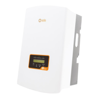
3) Strip the ground cable insulation to a suitable length(see Figure 5.8).
Figure 5.8 suitable length
Important:
Figure 5.9 strip wire
Important:
For multiple inverters in parallel , all inverters should be connected to the
same ground point to eliminate the possibility of a voltage potential existing
between inverter grounds.
B (insulation stripping length) is 2mm~3mm longer than A (OT cable
terminal crimping area) 2mm~3mm.
After crimping the terminal to the wire, inspect the connection to ensure the
terminal is solidly crimped to the wire.
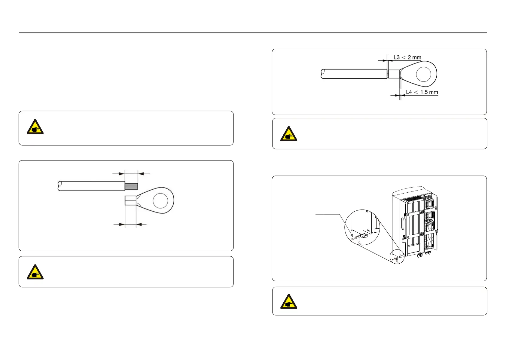
5) Remove the screw from the heat sink ground point.
6) Connect the grounding cable to the grounding point on the heat sink,and tighten the
grounding screw, Torque is 3Nm(see figure 5.10).
For improving anti-corrosion performance,
after ground cable installed, apply silicone or paint is preferred to protect.
Important:
4) Insert the stripped wire into the OT terminal crimping area and use the hydraulic
clamp to crimp the terminal to the wire (see Figure 5.9).
Figure 5.10 Fixed cable
Grounding screw
To effectively protect the inverter, two grounding methods must be performed.
Connect the AC grounding cable (Please refer to section 5.3.3).
Connect the external grounding terminal.
To connect the grounding terminal on the heat sink, please follow the steps below:

 Loading...