EasyManuals Logo

SOLIS S6 Series Manual

SOLIS S6 Series
50 pages
To Next Page IconTo Next Page
To Previous Page IconTo Previous Page
Page #13 background imageLoading...
Page #13 background image
User Manual
4. Installation
12
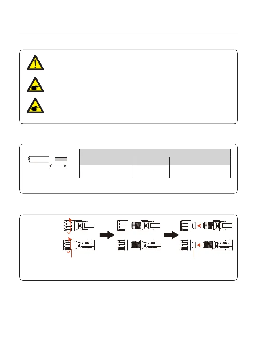
4.4 PV Input Cable Installation
Negative terminal
Positive terminal
Before connecting inverter, please make sure the PV array open circuit
voltage is within the limit of the inverter.
Before connection, please make sure the polarity of the output voltage of
PV array matches theDC+andDC-symbols.
Please use approved DC cable for PV system.
4.0~6.0
4.012AWG
(12~10AWG)
Cable type
Cross sectionmm²
Range
Industry generic PV cable
Recommended value
1. Select a suitable DC cable and strip the wires out by 7±0.5mm. Please refer to the table
below for specific specifications.
7±0.5mm
2. Take the DC terminal out of the accessory bag, turn the screw cap to disassemble it,
and take out the waterproof rubber ring.
Nut Waterproof collar
Figure 4.6
Figure 4.7

Other manuals for SOLIS S6 Series

Questions and Answers:

Question and Answer IconNeed help?

Do you have a question about the SOLIS S6 Series and is the answer not in the manual?

SOLIS S6 Series Specifications

General IconGeneral
Number of MPPTs2
THDi<3%
DC SwitchYes
Max. AC Output Power6000W
Rated AC Output Power6000W
Max. AC Apparent Power6000VA
Rated Grid Voltage230V
Grid Voltage Range180V-280V
Rated Grid Frequency50Hz/60Hz
Grid Frequency Range45-55Hz / 55-65Hz
ProtectionDC Reverse-Polarity Protection, AC Short-Circuit Protection
Operating Temperature Range-25°C to 60°C
CoolingNatural Cooling
CommunicationWiFi/GPRS

Related product manuals