User Manual
4. Installation
18
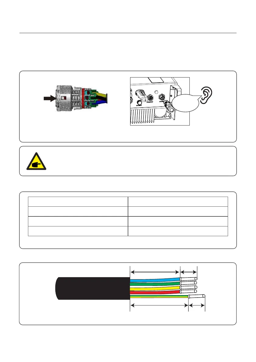
Figure 4.22
NOTE:
A continuity test shall be made to ensure that the correct terminations have
been made after field wiring.
6. Push the AC Grid Connector into the AC Grid Port on the inverter and rotate the rotatory
ring on the AC Grid connector to the direction as marked “LOCK” on the connector.
(Hold the Body while rotating the ring).
Click
4.6.2 AC Backup Port Connection
Describe
Cable diameter
6mm²
7mm
Traverse cross sectional area
Exposure Length
Numerical value
Table 4.2
1. Strip the AC wires about 7mm.
Figure 4.23
18mm
23mm 7mm
7mm
14~17mm
 Loading...