switch integrated. If not, an external DC switch of proper
ratings should be used.
6.6.2 BMS Communication Connection
Please check whether the BMS communication cable in the
accessory box is appropriate for the battery. If you are not sure
for that, please confirm with your battery vendor.
Procedure:
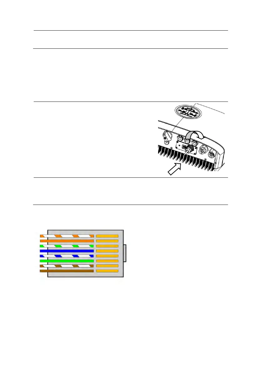
STEP 1:
• Please insert the RJ45
connector with water-proof cap
into the port marked with “BMS”
on inverter and fasten the cap.
STEP 2:
• Please insert the other end of the cable in the
corresponding port in battery.
BMS Connector Pin Definition:
1. BMS_CAN_H
2. BMS_CAN_L
3. BMS_485_A
4. GND
5. BMS_485_B
6. GND
7. NULL
8. NULL