20
85DR-C
1 4
DIMM1
DIMM2
1
mPGA478B
Intel RG82845-D
Intel RG82845
1 3
FAN2
1 3
FAN3
1 3
FAN1
AGP 4X
PCI 1
PCI 2
PCI 3
PCI 4
PCI 5
PCI 6
FWH
WOL1
1 3
LPC I/O
Controller
AC'97
Codec
CNR
SW1
ON
DIP
1 2 3 4 5
IDE2
IDE1
1
1
1
FDC1
Li
Battery
82801BA
JBAT1
1 3
JP3
JP4
1 3
1 3
JP13
1 3
JP2
1 3
1 3
1 3
RT2
RT1
Peripheral Power Connector
+12 Power Connector
4 3
2 1
Main Power Connector
USB1
1
16
PS/2
MOUSE
PS/2
K/B
upper
lower
USB1
USB0
upper
lower
LPT1
COM1COM2
MIC
GAME/MIDI PORT
LINE
OUT
LINE
IN
NJP1
SPEAK RST KEYLOCKPWR/LED SUS_LED
IDE_LED
IR PWR SMI
30
1
++
--
+
-
CD9
CD10
1 4
JAGP1
JAGP2
LED1
SCR1
CMEM1
1
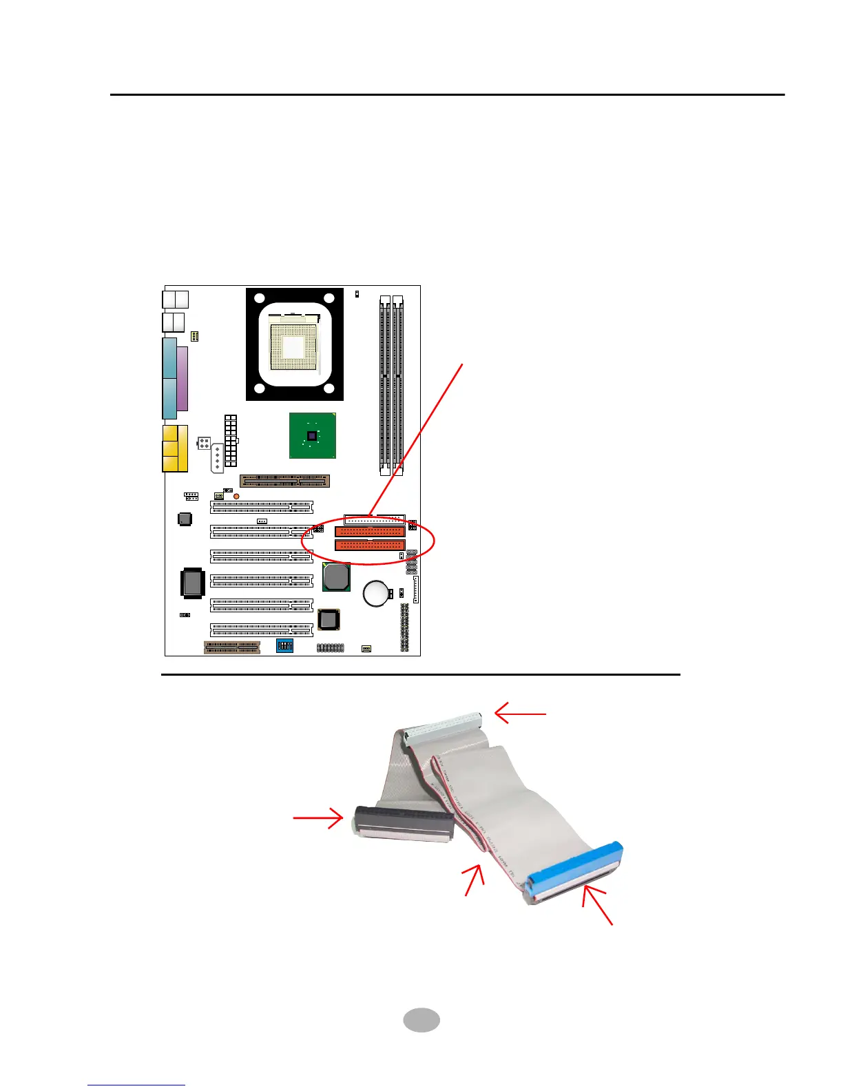
• To install HDD (Hard Disk Drive), you may connect the connector of IDE
cable to the primary (IDE1) or secondary (IDE2) connector on board, and
then connect the gray connector to your slave device and the black
connector to your master device. If you install two hard disks, you must
configure the second drive to Slave mode by setting its jumpers correctly.
Please refer to your hard disk documentation for the jumper settings.
Hard Disk Drive Connector:
Orient the red line on the IDE
ribbon cable to Pin1.
2-5 HDD/FDD Installation
Gray connector
Blue connector
IDE Cable
Black connector
red line