30
85DR-C
1 4
DIMM1
DIMM2
1
mPGA478B
Intel RG82845-D
Intel RG82845
1 3
FAN2
1 3
FAN3
1 3
FAN1
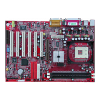
AGP 4X
PCI 1
PCI 2
PCI 3
PCI 4
PCI 5
PCI 6
FWH
WOL1
1 3
LPC I/O
Controller
AC'97
Codec
CNR
SW1
ON
DIP
1 2 3 4 5
IDE2
IDE1
1
1
1
FDC1
Li
Battery
82801BA
JBAT1
1 3
JP3
JP4
1 3
1 3
JP13
1 3
JP2
1 3
1 3
1 3
RT2
RT1
Peripheral Power Connector
+12 Power Connector
4 3
2 1
Main Power Connector
USB1
1
16
PS/2
MOUSE
PS/2
K/B
upper
lower
USB1
USB0
upper
lower
LPT1
COM1COM2
MIC
GAME/MIDI PORT
LINE
OUT
LINE
IN
NJP1
SPEAK RST KEYLOCKPWR/LED SUS_LED
IDE_LED IR PWR SMI
30
1
++
--
+
-
CD9
CD10
1 4
JAGP1
JAGP2
LED1
SCR1
CMEM1
1
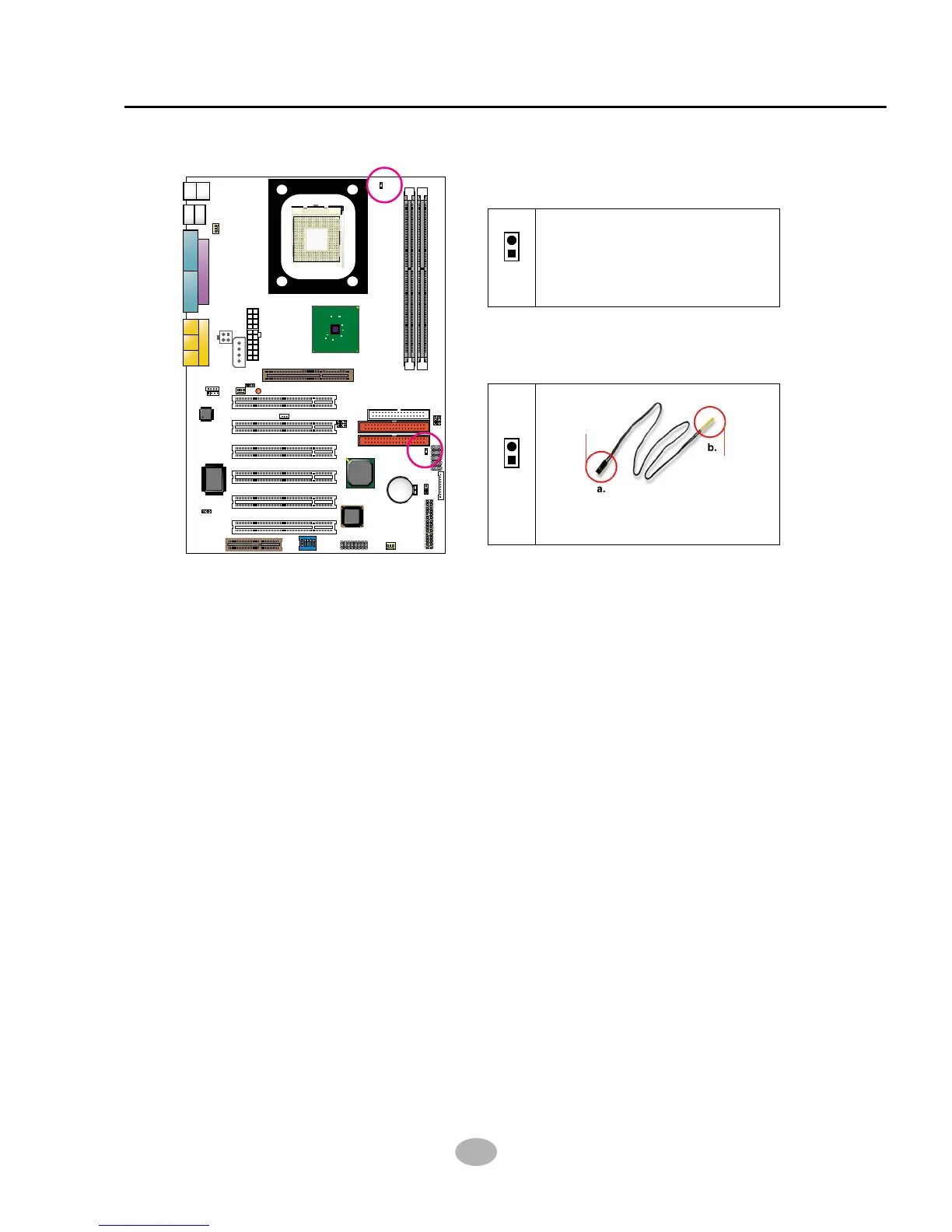
2-7.4 Thermal Sensor Connector RT2 (Optional)
1. Connector RT1: A blue thermal resistor is already soldered to connector
RT1 so as to sense the temperature round the mainboad. What RT1
does is to transmit the thermal signal to BIOS or Hardware Monitor.
2. Connector RT2: A thermal cable is needed to connect RT2 to on-board
devices such as HDD, Graphics card etc., so as to detect the temperature
generated therein. Please connect the end (a) of the thermal cable to
mainboard RT2 header, and tape another end (b) of thermal cable on to
the device which you want to monitor. After you have finished the thermal
cable installation, you will see the detected temperature in BIOS setup
or Hardware monitor utility.
RT1 mounted with blue
Thermal Resistor.
RT1
Thermal Cable
To Devices
To RT2
RT2