27
Chapter 2 Hardware Setup
1 4
DIMM1
DIMM2
1
mPGA478B
Intel RG82845-D
Intel RG82845
1 3
FAN2
1 3
FAN3
1 3
FAN1
AGP 4X
PCI 1
PCI 2
PCI 3
PCI 4
PCI 5
PCI 6
FWH
WOL1
1 3
LPC I/O
Controller
AC'97
Codec
CNR
SW1
ON
DIP
1 2 3 4 5
IDE2
IDE1
1
1
1
FDC1
Li
Battery
82801BA
JBAT1
1 3
JP3
JP4
1 3
1 3
JP13
1 3
JP2
1 3
1 3
1 3
RT2
RT1
Peripheral Power Connector
+12 Power Connector
4 3
2 1
Main Power Connector
USB1
1
16
PS/2
MOUSE
PS/2
K/B
upper
lower
USB1
USB0
upper
lower
LPT1
COM1COM2
MIC
GAME/MIDI PORT
LINE
OUT
LINE
IN
NJP1
SPEAK RST KEYLOCKPWR/LED SUS_LED
IDE_LED IR PWR SMI
30
1
++
--
+
-
CD9
CD10
1 4
JAGP1
JAGP2
LED1
SCR1
CMEM1
1
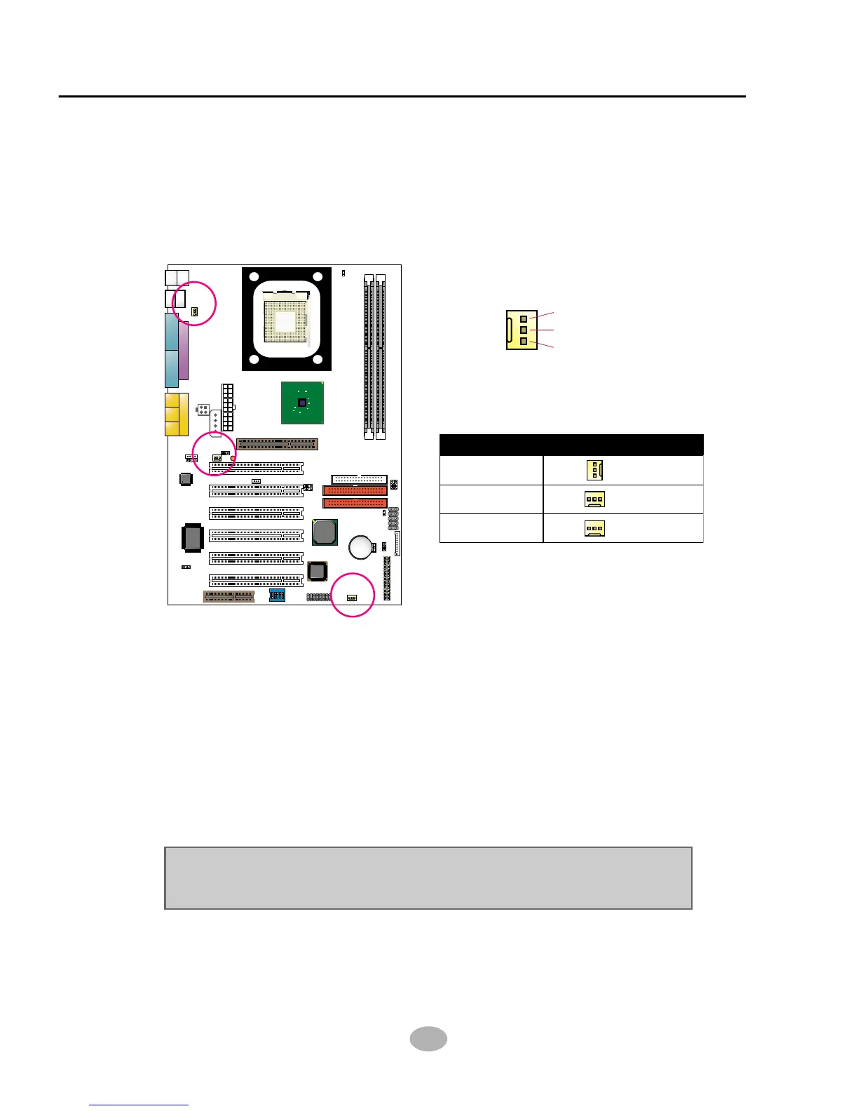
These fan connectors support CPU/System/chassis cooling fan with +12V.
When connecting wire to FAN connectors, users should pay attention
that the red wire is for the positive current and should be connected to
pin +12V, and the black wire is Ground and should be connected to pin
GND. If your mainboard has Hardware Monitor chipset on-board, you
must use a specially designed fan with speed sensor to take advantage
of this function.
For fans with speed sensors, each rotation of the fan blades will send out
2 electric pulses, by which System Hardware Monitor will work out the
fan rotation speed by counting the pulses.
NOTE : We use 3 “Yellow” fan connectors to mark that they support fan
speed sensor function.
2-7.1 On Board FAN Connectors (FAN1,FAN2, FAN3)
2-7 Other Connectors Configuration
• This section lists out all connectors configurations for users’ reference.
GND
+12V
SENSOR
FAN2
FAN3
FAN1
CPU FAN
SYSTEM FAN
CHASSIS FAN
FAN1, FAN2, FAN3: On-Board FAN Connectors