37
Chapter 2 Hardware Setup
1
16
VCC
USB Port3 Data+
USB Port2 Data+
USB Port3 Data-
USB Port2 Data-
GND
GND
VCC
GND
GND
1
16
1
Additional USB Cable
(Optional)
red wire
USB Header Pin Assignment
USB Port
1 4
DIMM1
DIMM2
1
mPGA478B
Intel RG82845-D
Intel RG82845
1 3
FAN2
1 3
FAN3
1 3
FAN1
AGP 4X
PCI 1
PCI 2
PCI 3
PCI 4
PCI 5
PCI 6
FWH
WOL1
1 3
LPC I/O
Controller
AC'97
Codec
CNR
SW1
ON
DIP
1 2 3 4 5
IDE2
IDE1
1
1
1
FDC1
Li
Battery
82801BA
JBAT1
1 3
JP3
JP4
1 3
1 3
JP13
1 3
JP2
1 3
1 3
1 3
RT2
RT1
Peripheral Power Connector
+12 Power Connector
4 3
2 1
Main Power Connector
USB1
1
16
PS/2
MOUSE
PS/2
K/B
upper
lower
USB1
USB0
upper
lower
LPT1
COM1COM2
MIC
GAME/MIDI PORT
LINE
OUT
LINE
IN
NJP1
SPEAK RST KEYLOCKPWR/LED SUS_LED
IDE_LED
IR PWR SMI
30
1
++
--
+
-
CD9
CD10
1 4
JAGP1
JAGP2
LED1
SCR1
CMEM1
1
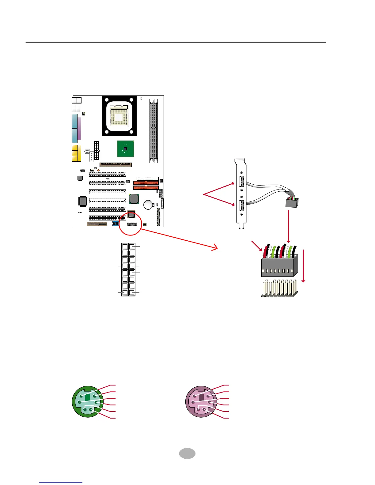
• When plugging the USB cable into Header USB1, users must make sure
the red wire is connected to the first pin.
2-7.10 USB Header (Header USB1)
• This header is for providing you two additional USB ports by using an
additional USB Cable. User can order the additional USB cable from
your mainboard dealers and venders.
2-7.11 PS/2 Mouse And PS/2 Keyboard
Header USB1
PIN 6 : None
PIN 5 : Mouse Clock
PIN 4 : Vcc
PIN 3 : GND
PIN 2 : None
PIN 1 : Mouse Data
PS/2 MOUSE
PIN 6 : None
PIN 5 : Keyboard Clock
PIN 4 : Vcc
PIN 3 : GND
PIN 2 : None
PIN 1 : Keyboard Data
PS/2 KEYBOARD