34
85DR-C
1 4
DIMM1
DIMM2
1
mPGA478B
Intel RG82845-D
Intel RG82845
1 3
FAN2
1 3
FAN3
1 3
FAN1
AGP 4X
PCI 1
PCI 2
PCI 3
PCI 4
PCI 5
PCI 6
FWH
WOL1
1 3
LPC I/O
Controller
AC'97
Codec
CNR
SW1
ON
DIP
1 2 3 4 5
IDE2
IDE1
1
1
1
FDC1
Li
Battery
82801BA
JBAT1
1 3
JP3
JP4
1 3
1 3
JP13
1 3
JP2
1 3
1 3
1 3
RT2
RT1
Peripheral Power Connector
+12 Power Connector
4 3
2 1
Main Power Connector
USB1
1
16
PS/2
MOUSE
PS/2
K/B
upper
lower
USB1
USB0
upper
lower
LPT1
COM1COM2
MIC
GAME/MIDI PORT
LINE
OUT
LINE
IN
NJP1
SPEAK RST KEYLOCKPWR/LED SUS_LED
IDE_LED
IR PWR SMI
30
1
++
--
+
-
CD9
CD10
1 4
JAGP1
JAGP2
LED1
SCR1
CMEM1
1
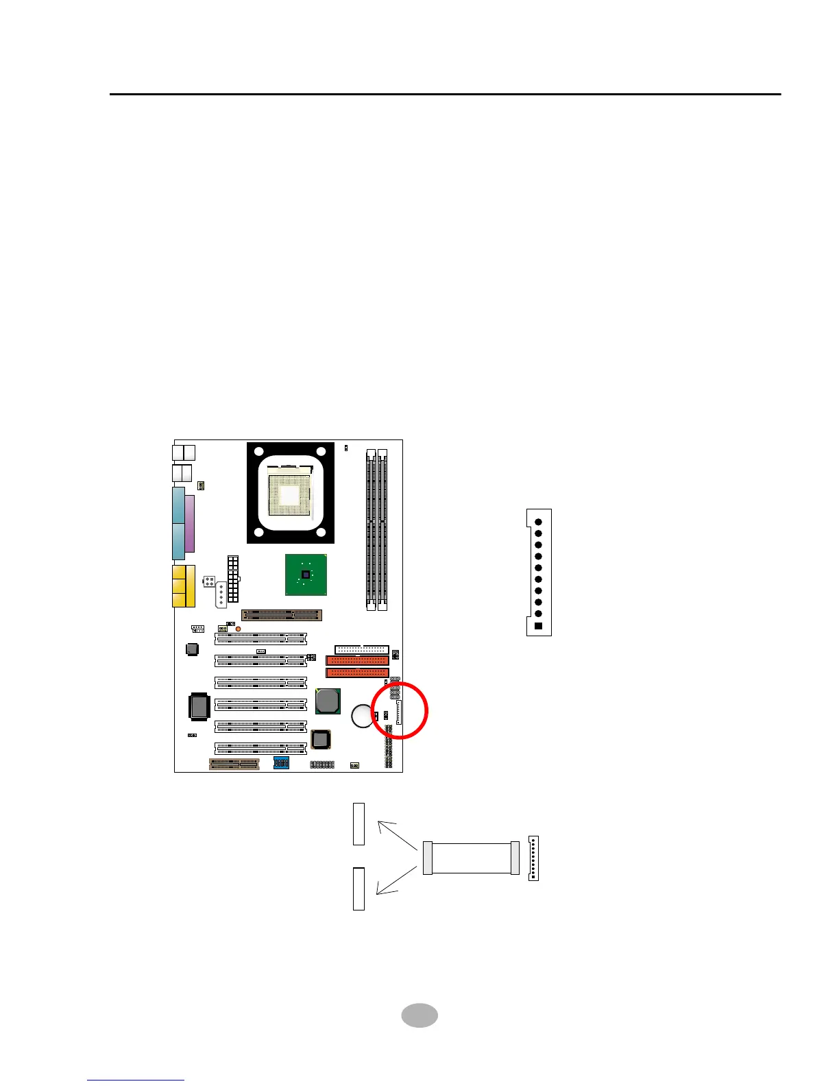
2-7.7 CMEM1 Memory Stick™/Secure Digital Memory Card Reader
Connector
• This connector can be connected to a Memory Stick Reader or Secure
Digital memory card reader with a Memory Stick/Secure Digital memory
card cable connector.
• JP13 is designed on board for Memory Stick/Secure Digital memory card
select for this connector. Before you set up connection from CMEM1 to
a Memory Stick Reader or a secure Digital Memory Card Reader, you
should choose the right setting of Jp13. Please see Jumper setting of
Jp13 for more detailed instruction.
• Besides JP13 setting, user should also adjust an option “MS/SD Port
Mode” in “Integrated Peripheral” of BIOS setup to select “MS socket” or
“SD socket”. (see “Integrated Peripheral” in BIOS setup.)
• Meeting SONY Memory Stick™ specification Version 1.03.
CMEM1 pin assignment
GND
MS1/SD1
VCC3
MS2/SD2
MS3/SD3
MS4/SD4
MS5/SD5
MS/SDCLK
MS/SDPWCTL#
MS/SDRWLED
CMEM1
MS/SD Cable
Secure Digital Memory Reader
Memory Stick Reader
Connection between CMEM1 connector and MS/SD Card Reade