Section 3 A-Scan Operation and Clinical Use
There are a few common errors which may
occur when performing A-scans which deserve
some mention. These errors are described
below.
CORNEAL COMPRESSION
One of the most common mistakes made when
performing axial length measurements is
applying excessive pressure on the eye with the
probe. When using a Direct Contact Probe (and
to a lesser extent the Soft-Touch Probe) it is
possible to indent the cornea to the extent that
the measurements will be adversely affected.
In using the Direct Contact Probe extreme care
should be taken to insure that only enough force
necessary to maintain contact with the cornea is
used. The problem is minimized to some degree
in the case of the Soft-Touch probe since
excessive pressure is evidenced by the fact that
the probe will begin to recede into its housing.
Checking the measured ACD values listed in the
Measure Scan screen for any inconsistencies
will generally indicate whether or not there is
sufficient corneal compression to require
deleting that particular scan from the group.
A-SCAN PATTERN
Recognizing an optimal echo pattern is the basis
for performing accurate A-scan measurements.
Even when using one of the automatic modes
the user should review each scan to determine
whether or not the scan pattern is acceptable. It
is important to remember that the automatic
modes are meant to facilitate the examination
procedure but not replace the examiner's clinical
judgment. The examination results should not
be blindly accepted and by reviewing the scans
the user will reduce the possibility of any errors
which may cause less than optimal results. In
reviewing, the user should compare the
similarity of the characteristics of the particular
scan under consideration with those of an
optimal A-Scan pattern.
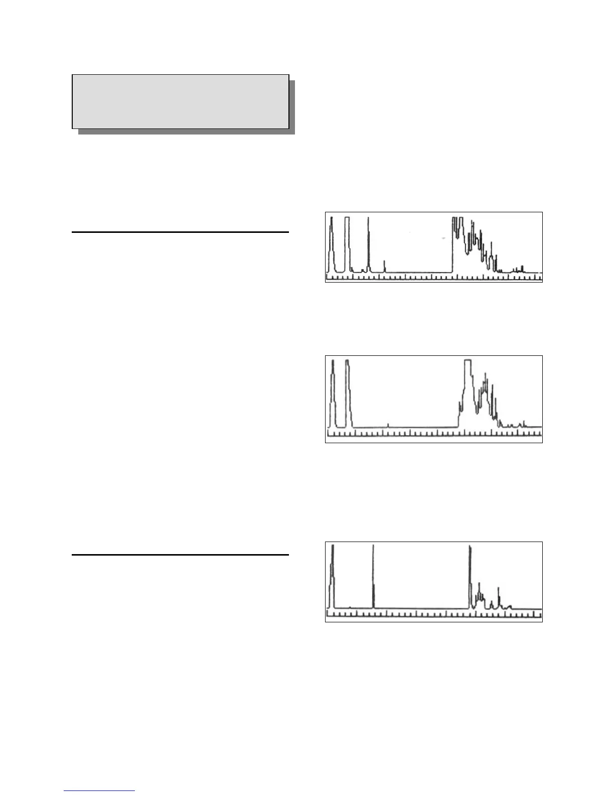
Characteristics of an Optimal A-Scan are as
follows:
1. The cornea, lens and retinal echoes should
all be approximately the same height.
Figure 3-11. Correct A-Scan Pattern.
2. The retinal echo should rise sharply from the
baseline forming a 90º angle.
Figure 3-12. Poor Retinal Rise
3. The orbital pattern beyond the Retina should
present a gradual decline. A sharp drop in
this pattern may indicate that the probe is not
aligned along the visual axis.
Figure 3-13. Poor Retinal Decline
The user should always strive to achieve these
three basic criteria before accepting any
measurements as accurate. Some anatomical
variations may prevent all such criteria from
being simultaneously achieved in any given
3.6
SOURCES OF ERRORS AND HOW
TO AVOID THEM
Doc # 0300-A-1901-3D 3 - 11
 Loading...