M2-M Operating Manual | Mounting and Connecting
M2-M_Operating_Manual_2.0.0
3.2.10 EXTERNAL POTENTIOMETER
For brightness control an external potentiometer can be connected to the monitor. In order to be automatically
recognized, the electrical resistance of the potentiometer must have a certain value.
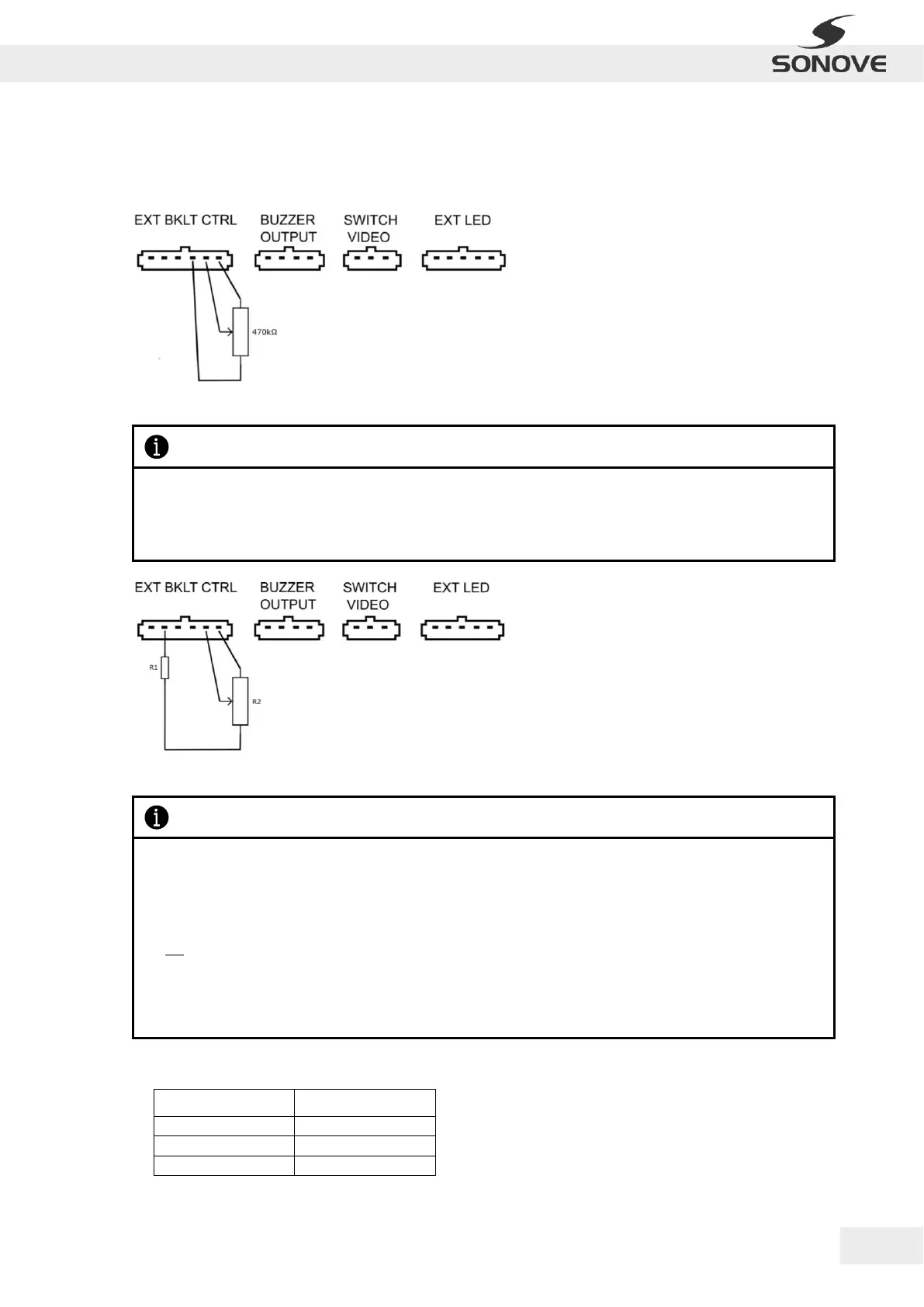
Figure 18: Connecting diagram for potentiometers with an electrical resistance of 470 kΩ
Figure 19: Connecting diagram for potentiometers that DO NOT have an electrical resistance (R2) of 470 kΩ
The following potentiometers and corresponding series resistors have been tested:
Table 4: Tested values of series resistors for common potentiometers
Please notice, that the connected potentiometer must have an electrical resistance of 470 kΩ in order to be
automatially recognized.
The connecting diagram for potentiometers with an electrical resistance of 470 kΩ is shown in figure 18.
Please notice, that the usage of potentiometers that DO NOT have an electrical resistance (R2) of 470 kΩ
requires the connection of a series resistor (R1).
In this case the resistance ratio must be as follows:
𝑅2
𝑅1
= 141
The connecting diagram for potentiometers that DO NOT have an electrical resistance (R2) of 470 kΩ is
shown in figure 18.
 Loading...