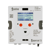
23Instruction for use | Supercal 5
For installing the heat meter and the associated subassemblies, the general regulations,
according to EN1434-Part 6, must be observed.
5.2 Opening the Calculator
To connect the inputs and outputs, remove the calculator cover.
5.3 Wiring
Overview of the connections:
5. Wiring
5.1 Wiring Requirements
1
À
1
\
�
-
V
✓
1
,� î)
C
C
C
c
C
C
@
,
,
i
�
:
) (
�
J
-
V V
V
<
X
\
1 5 6 2 3 7 8 4 10 11 9 13 50 51 52 53 24 25 16 17 18 19
,�
î)
Terminal Designation Description
Inputs
5, 6
2-wire technology Temperature high
1, 5 and 6, 2 4-wire technology
7, 8 2-wire technology Temperature low
3, 7 and 4, 8 4-wire technology
10
11 (-)
50 Pulse inputs
51 (-) pulse input additional pulse input 1
52
53 (-) pulse input additional pulse input 2
Outputs
16
Energy-, volume- or tariff counter
17 (-) open-collector outputs 1
18
(-) open-collector output 2
M-Bus
24 M-Bus (polatity independent)
Embedded M-Bus
25 M-Bus (polarity independent)
Danger due to electrical voltage!
The entire electrical system must be voltage-free.
Additional Electrical Information
Before commissioning, ensure the supply voltage conforms to the information in the nameplate.
Provide a suitable switch or circuit breaker in the building installation. This switch must be installed easily
accessible near the device and marked as a disconnecting device.
Overcurrent protection (<= 10A) must be installed in the mains cable.

 Loading...