Do you have a question about the Sony CDP-101 and is the answer not in the manual?
Detailed technical specifications including system, disc, laser, outputs, and power requirements.
Critical component safety warning regarding replacement parts.
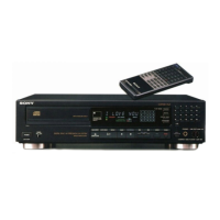
Details on sound quality, loading mechanism, feather touch, AMS, display, and remote control.
List of other features like timer play, auto pause, and accessory connector.
Information on model identification labels for different regions.
Important precautions for servicing, disc handling, and moisture condensation.
Instructions for connecting the unit and overview of controls and functions.
Explanation of player operations and the system's block diagram.
Caution and procedure for preventing damage from static electricity.
Specific instructions for safely handling the KSS-100A optical pick-up block.
General precautions for handling MOS ICs due to insulation sensitivity.
Step-by-step precautions for safely replacing MOS ICs.
Precautions for checking C-MOS ICs to avoid damage.
Important note on safe observation of laser diode emission.
Procedure to verify the laser diode is emitting light.
Procedure to check the focus search operation of the optical block.
Notes on positioning the unit when the bottom plate is removed.
Diagrams showing the location of internal components like boards, switches, and motors.
Precautions for installation, operation, and cleaning the unit.
Guidelines for handling, cleaning, and storing compact discs.
Information on moisture condensation and how to resolve it.
Details on laser diode properties, output, and safety classification.
Examples and information on laser warning labels affixed to the unit.
Post-service safety check procedure for the US model.
Detailed procedure for testing AC leakage current from metal parts.
Instructions for connecting the player to an amplifier and power source.
Information on the AC outlet's capacity and power cord polarity.
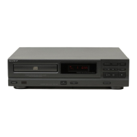
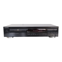
Identification and function of all front panel controls and indicators.
Explanation of display indicators and rear panel connections/switches.
Step-by-step guide for playing, stopping, pausing, and resetting discs.
How to search for specific selections or points within a selection.
Details on repeating selections, whole disc, or A→B points, and how to cancel.
How to monitor time and set up timer-activated playback.
Steps for connecting and preparing for synchronized playback.
General instructions and reference for the disassembly process.
Detailed diagrams showing disassembly steps and wiring connections.
Instructions for removing the bottom plate, loading board, and motors.
Steps for removing the case, eject board, disc motor, and servo amp board.
Instructions for removing the mechanism section and chucking switch board.
Steps for removing the audio amp, in switch, and optical pick-up block.
Procedure for assembling the optical pick-up block and checking gain.
Instructions for removing the front panel and indication board.
Steps for removing power/timer switch boards, loading motor, and headphone board.
Section covering various mechanical adjustments for the player.
Procedure to adjust the optical pick-up position for accurate disc reading.
Procedure to adjust the thrust of the optical sled motor.
Procedure to adjust the height of the disc pulley.
Procedure to adjust the guide plate to suppress lateral play.
Procedure to adjust the disc table stopper to prevent forward movement.
Section detailing electrical adjustments and calibration procedures.
Setting the adjustment mode by connecting test points TP2 and TP4.
Electrical adjustment related to optical pick-up position control.
Procedure to adjust the RF offset on the audio amp board.
Procedure to adjust the tracking offset on the audio amp board.
Procedure to adjust the focus bias on the servo and audio amp boards.
Procedure to adjust the RF PLL circuit parameters.
Procedure to adjust the phase lock for IC201.
Procedure to adjust the AF offset on the audio amp board.
Procedure for adjusting focus and tracking gain, with reference notes.
Detailed procedure and symptoms for focus/tracking gain adjustment.
Procedure for adjusting IC201 phase lock with waveform examples.
Procedure for AF offset adjustment with waveform examples.
A simpler method for focus/tracking gain adjustment.
Mounting diagram for the servo amp section.
Detailed wiring diagrams for various sections of the player.
Mounting diagram for the audio amp section.
Lead layouts for various semiconductors used in the unit.
Exploded views of the unit showing component assembly.
Additional exploded views illustrating component placement.
Exploded views detailing parts of the front panel and rear assembly.
Exploded views showing various assemblies and components.
Exploded views illustrating mechanical components and their arrangement.
Exploded views showing motor assemblies and switch boards.
Exploded views detailing the optical block and sensor components.
List of general hardware components like screws, springs, and retainers.
Information on capacitors, resistors, coils, and semiconductors.
List of general electrical parts including screws, holders, and labels.
List of capacitors with their part numbers and specifications.
List of diodes and integrated circuits with part numbers.
List of ICs, motors, and switches with part numbers.
List of transistors and resistors with part numbers and values.
List of switches, resistors, buzzers, relays, oscillators, and fuses.
Description and illustration of various screw types used in the unit.
Description and illustration of nuts, washers, and retaining rings.
Specifications for the RM-101 remote control system.
Explanation of the functions of each key on the remote commander.
Notes on remote control range, usage, and disassembly procedure.
Summary of the CX7947 LSI, pin functions, and data codes.
Details on mode switching, transmission codes, and key matrix waveforms.
Explanation of the order and timing of output data.
Description of indication output behavior during remote control operation.
Mounting and schematic diagrams for the remote control circuit.
Exploded view and parts list for the remote control unit.
| Type | Compact Disc Player |
|---|---|
| Signal-to-Noise Ratio | 90 dB |
| Total Harmonic Distortion | 0.05% |
| Dynamic range | 90 dB |
| Channel separation | 90 dB |
| Disc format | CD |
| Digital-to-Analog Converter | 16 bit linear |
| Frequency Response | 20Hz - 20kHz |
| Output | 2V RMS |
| Line output | 2V |