– 19 –
SECTION 4
TEST MODE
4-1. AF MODE
Connect the TP19 (AFADJ) on the BD board to the ground and
turn on the power supply.
The AF mode is then activated and the following check can be
made.
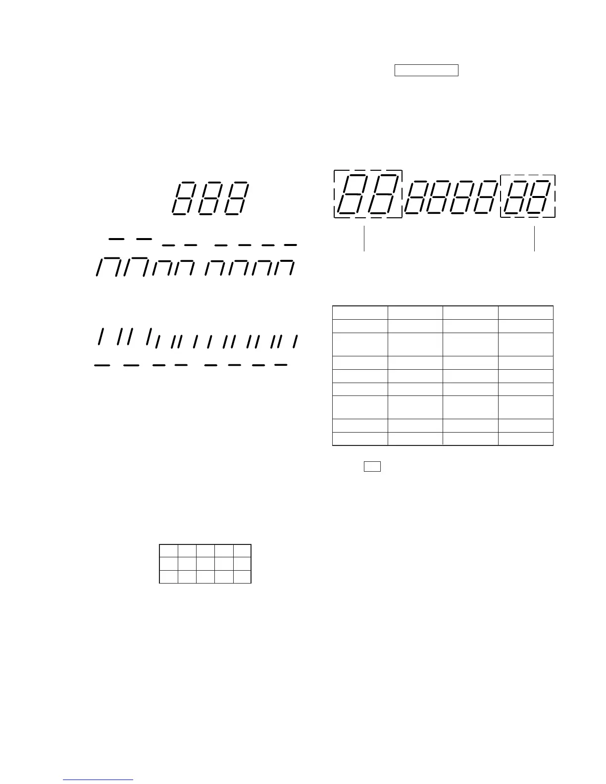
4-1-1. Fluorescent Indicator Tube Check
After confirming display of all on, keep pressing the following
button, and the following display is attained.
p (STOP) button
(Display: 01)
” (PLAY) button
(Display: 02)
P
(PAUSE) button
(Display: 03)
) button
0 button
SHUFFLE
REPEAT
A-
AUTO SPACE
EDIT
STEP
–
PROGRAM
INDEX
1
B
(JUST)
PEAK
CHECK button
135
79
11 13 15
(Display: 04)
(Display: 05)
(Display: 06)
24
6810
12 14 ”
CLEAR button
(Display: 07)
Keep pressing the §OPEN/CLOSE button, and all on display is
attained again.
4-1-2. Key Check
All buttons are assigned with numbers respectively, and when each
button is pressed, it is counted and its number is displayed. Up to
“16” can be counted.
A button pressed once is not further counted but the number is
displayed. (Table 4-1)
(
(
count display
button number
display
Button Display Button Display
ERASE 00 P 03
EDIT/
12 ) 04
TIME FADE
FILE 13 0 05
FILTER 20 CHECK 06
ENTER 23 CLEAR 07
6 all light
P MODE 09
OPEN/CLOSE up
p 01 REPEAT 10
( 02 TIME 11
4-1-3. Remote Commander Check
Press the ( button on remote commander, and “ ˚ ” ( on the
set turn on. Nothing will be displayed if pressing another button.
Table 4-1.
 Loading...