– 28 –
Main Ports
SPDL-MUTE (pin !¶)
From the viewpoint of performance of the set, the disc must
not move nor sway when the disc table opens. These
problems however occur in the actual case due to the offset
voltage generated and the voltage generated because of the
positional relation between the BSL coil and Hall element.
The spindle motor driver (IC102, IC104) is therefore mute
(Estimate).
The spindle
motor driver is
muted during
this time.
BLANK (pin @¡)
This port is required because the display tube in this set static
lights up and a dedicated screwdriver is required. It is
basically a RESET pin. But as problems will occur if use
also as RESET, timings are specially provided using the
micro-processor.
SENSER (pin @•)
The results of the detection of IC361 IS471F is output to this
pin. It becomes “L” when there is no stabilizer (when light
reaches). The next process of imposing the next focus is not
performed. (Effective only when pin @¶ is “H”.)
Therefore, it must be noted that if PLAY is performed when th
servo board at the top of the CDM is not assembled properly,
the detection circuit operates and this pin does not operate.
It is does not operate, refer to 1. SERVICING NOTES ” Prep-
arations for Adjustment and Measurement” on page 3.
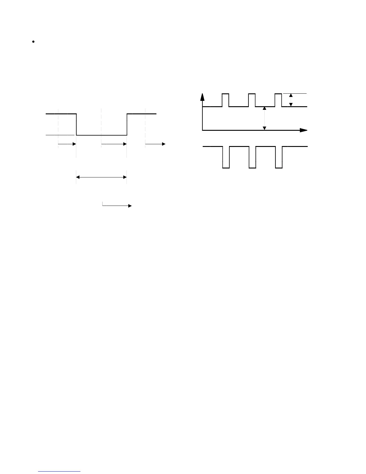
GLout pin
output waveform
SENSER SW (pin @¶)
As IC361 IS471F operate in pulse as shown in the figure, the
sound quality may be affected if operated constantly. As the
purpose of IC361 is to detectif the presence of the stabilizer,
it should be operated only when the tray is drawn in. IC361
operates as it is “H” only at this time. Normally it is “L”.
Ee
0
Eep
Eed
Time
Eep is the luminance of the signal light tuned with the low
level timing of the GLout pin output.
Eedis the luminance of the D.C. light. The light source is
the infrated-emitting diode (λp=940 nm).
*