– 15 –
SECTION 3
DISASSEMBLY
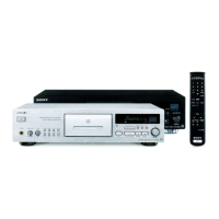
• This set can be disassembled in the order shown below.
Note:
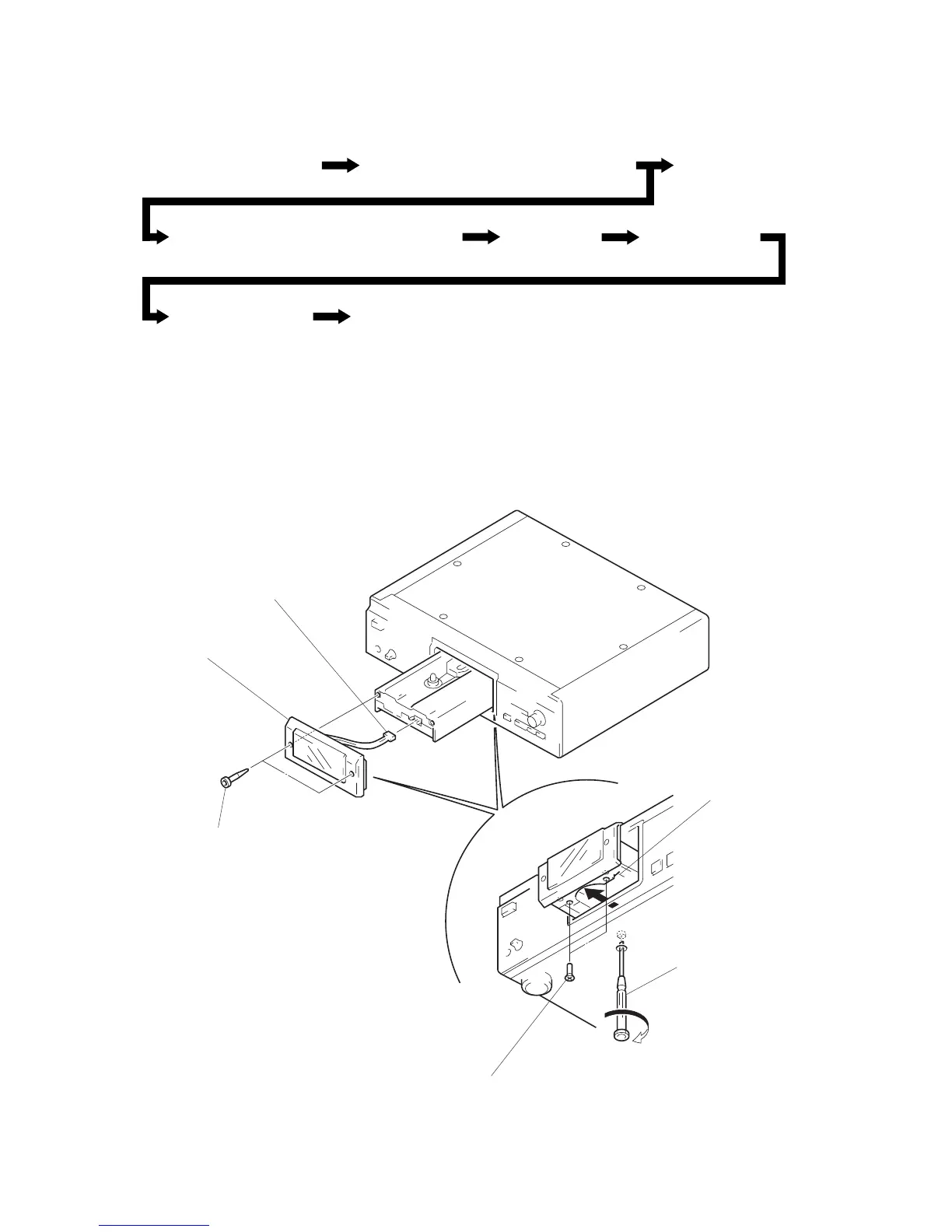
Follow the disassembly procedure in the numerical order given.
LOADING PANEL SECTION
LOADING PANEL SECTION
(Page 15)
CASE (TOP PLATE ), FRONT PANEL SECTION
(Page 16)
AUDIO BOARD
(Page 16)
MECHANISM DECK (CDM32BB-12B/CDM32BN-12B)
(Page 17)
SERVO BOARD
(Page 17)
PANEL (DRAWER)
(Page 18)
BASE UNIT (BU-12B)
(Page 18)
SLED MOTOR (M21), OPTICAL PICK-UP (KSS-273B/J1N)
(Page 19)
5
connector
(CN292)
4
loading panel section
3
two hexagon hole bolts
(LID) (for black/gold)
2
two screws
(KTP3
×
8) (for black/gold)
1
Open the tray turning the
tapering screwdriver to the
arrow direction.
tray
 Loading...