– 23 –
– 24 –
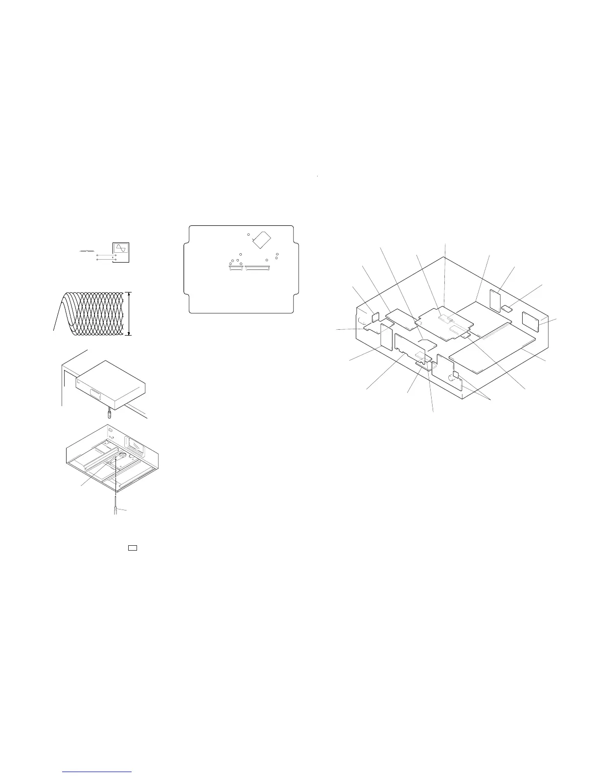
Skew Adjustment
Note : Do not perform the skew adjustment when not using at-
tached stabilizer to a set.
+
–
SERVO board
TP (RF)
TP (VC)
oscilloscope
(AC range)
VOLT/DIV: 200 mV
TIME/DIV: 500 ns
(with the 10: 1 probe
in use)
level: 1.2 Vp-p
+0.25
–0.20
RF signal waveform
[SERVO BOARD] – Conductor side –
TP (TEI)
IC101
SECTION 6
DIAGRAMS
• Circuit Boards Location
TP (RF)
TP (FE)
TP (RFI)
TP (TE)
TP (VC)
TP1 (ADJ)
TP2 (AFJ)
TP
(PLK)
29
(FEI)
CN101
CN102
1. Remove the bottom plate, put one third of the unit out from
the desk.
2. Connect the osiclloscope to TP (RF) and TP (VC) on SERVO
board.
3. Turned power switch on.
4. Put disc (YEDS-18) in and press the ( button.
5. Adjust to be clear the waveform of the oscilloscope turning
the adjsutment screw with a ‘ screwdriver.
Note: Clear RF signal waveform means that the shap “≈”can be
clearly distinguished at the center of the waveform.
6. After the adjustment, lock the adjustment screw.
LOADING MOTOR board
SERVO board
POWER board
COAX board
OPT board
LINE board
AUDIO board
FLEX RELAY board
KEY-L board
FL RELAY board
LOADING SW board
DISPLAY board
KEY-R board
VR board
SW board
BSL board
FUSE board
‘
screwdriver
adjustment screw