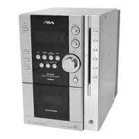
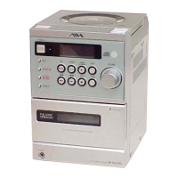
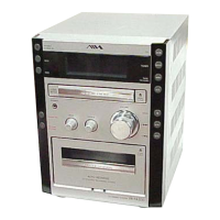
CX-JT7
2525
6-4. NOTE FOR PRINTED WIRING BOARDS AND SCHEMATIC DIAGRAMS
Note on Printed Wiring Board:
• X : parts extracted from the component side.
• Y : parts extracted from the conductor side.
• : Pattern from the side which enables seeing.
(The other layers' patterns are not indicated.)
Note on Schematic Diagram:
• All capacitors are in µF unless otherwise noted. pF: µµF
50 WV or less are not indicated except for electrolytics
and tantalums.
• All resistors are in Ω and
1
/
4
W or less unless otherwise
specified.
• 2 : nonflammable resistor.
• C : panel designation.
• A : B+ Line.
• B : B– Line.
•Voltages and waveforms are dc with respect to ground
under no-signal (detuned) conditions.
no mark : FM
(): CD PLAY
[]: TAPE PLAY (DECK-A)
{ } : TAPE PLAY (DECK-B)
〈〈 〉〉 : REC
∗
: Impossible to measure
•Voltages are taken with a VOM (Input impedance 10 MΩ).
Voltage variations may be noted due to normal produc-
tion tolerances.
•Waveforms are taken with a oscilloscope.
Voltage variations may be noted due to normal produc-
tion tolerances.
• Circled numbers refer to waveforms.
• Signal path.
F : TUNER (FM/AM)
J : CD PLAY
E : TAPE PLAY (DECK-A)
d : TAPE PLAY (DECK-B)
G : REC
j : MD (VIDEO) IN
N : MIC INPUT
•Abbreviation
E51 : Chilean and Peluvian models
MX : Mexican model
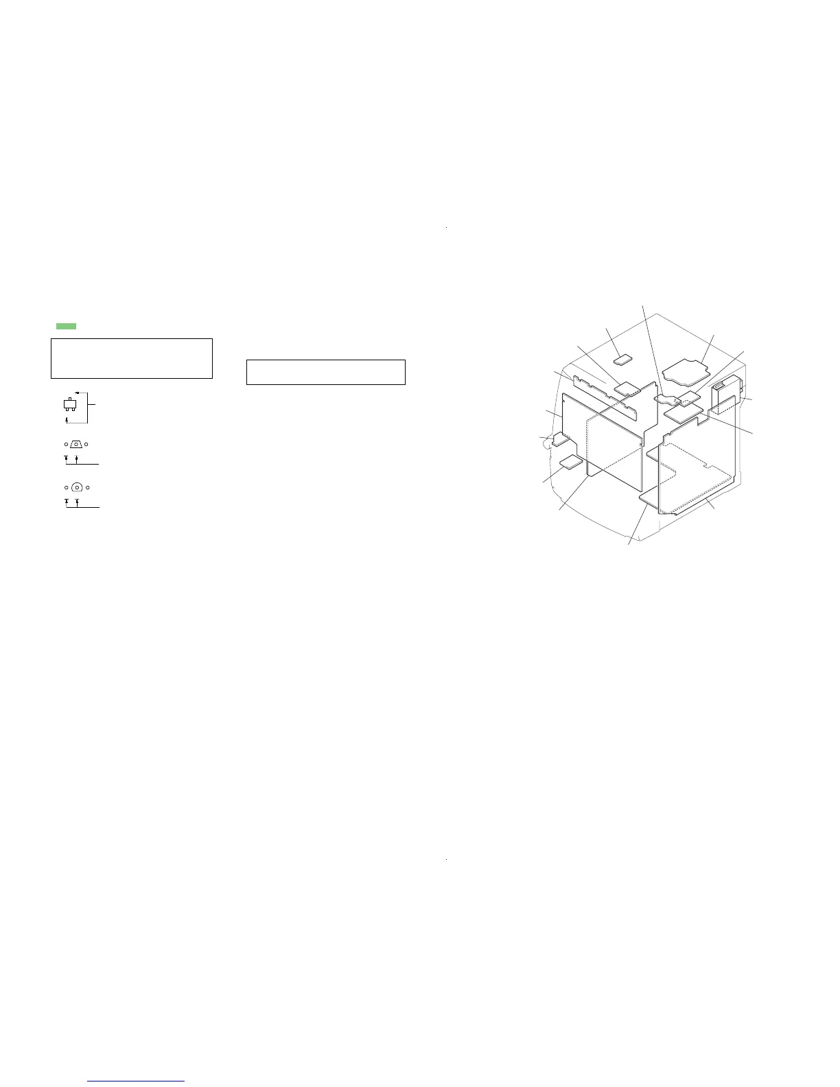
• Circuit Boards Location
Caution:
Pattern face side: Parts on the pattern face side seen from
(Conductor Side) the pattern face are indicated.
Parts face side: Parts on the parts face side seen from
(Component Side) the parts face are indicated.
C
B
These are omitted.
E
Q
B
These are omitted.
CE
Q
B
These are omitted.
CE
Q
• Indication of transistor.
Note: The components identified by mark 0 or dotted line
with mark 0 are critical for safety.
Replace only with part number specified.
BD board
MOTOR (TB) board
TUNER PACK
DRIVER board
MAIN board
POWER board
TRANSFORMER board
MICROPHONE board
(MX, E51)
HEADPHONE board
PANEL board
CD BUTTON board
MOTOR (LD) board
SW board
SENSOR board


 To Next Page