EasyManua.ls Logo

Sony DCR-TRV890E - CK-80 Board; LCD Panel Assembly, Hinge Assembly

Sony DCR-TRV890E
215 pages
Print Icon
To Next Page IconTo Next Page
To Previous Page IconTo Previous Page
Loading...
2-4
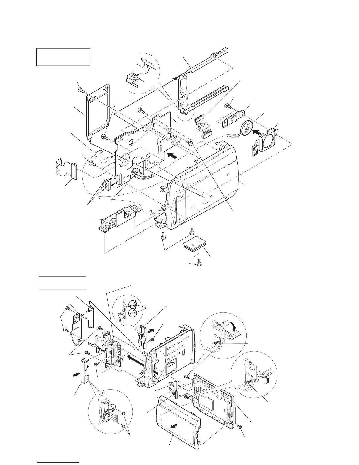
2-6. CK-80 BOARD
2-7. LCD PANEL ASSEMBLY, HINGE ASSEMBLY
CK-80
BOARD
2
PM cover
1
Screw (M2
×
3)
1
-
6
PM slider assembly
7
-
!¶
CK-80 board
!•
-
@¡
Speaker
7
Two screws
(M1.7
×
3)
!º
CK-80
board
!¶
Card ejector
(Slide it in the direction
of the arrow.)
!¡
Remove the
harness.
(SP-156)
6
PM slider assembly
8
Two screws
(M1.7
×
3)
5
Two screws (M2
×
3)
!§
Four screws (M2
×
7)
LCD panel assembly
!•
Two screws (M2
×
3)
!ª
Speaker fixing plate
@º
Speaker
@¡
SP folder
3
Two screws (M2
×
4)
4
Stand
9
Two screws
(M1.7
×
3)
!™
FP-16 flexible board
CN7202 6P
(CK-80 board)
!¢
FP-13 flexible board
CN7208 6P
(CK-80 board)
!∞
FP-9 flexible board CN7204 60P
(CK-80 board)
Insert the craw
into the slider
when re-assembling.
!£
Remove the harness
(CP-81, CP-82).
a
d
C
d
b
PD-101
BOARD
!º
LCD hinge lid
!¡
Blind plate
1
-
8
LCD panel block
9
-
!¶
Hinge assembly
!£
Hinge assembly
(Remove it in the direction
of the arrow
a
.)
Rotate it by 90
°
in the
direction of the arrow
b.
Rotate it by 90
°
in the
direction of the arrow
d
.
!§
Hinge cover (rear)
(Remove it while being
careful of the craw.)
!¶
Hinge cover
(front)
9
Three screws
(M2
×
3)
7
Two screws
(M2
×
3)
!∞
Two screws
(M1.7
×
3)
!¢
Screw (M1.7
×
3)
2
Screw
(M2
×
4)
3
Screw (M2
×
4)
8
LCD panel block
1
Two screws (M2
×
4)
4
P cabinet (C) assembly
!™
Three screws
(M2
×
3)
Craws
Rotate it by 90
°
in the direction
of the arrow
c
.
5
Remove the
CP-81 harness.
6
Remove
the CP-82
harness.

Table of Contents