13
Chapter 2 Locations and Functions of Parts and Controls
Chapter 2 Locations and Functions of Parts and Controls
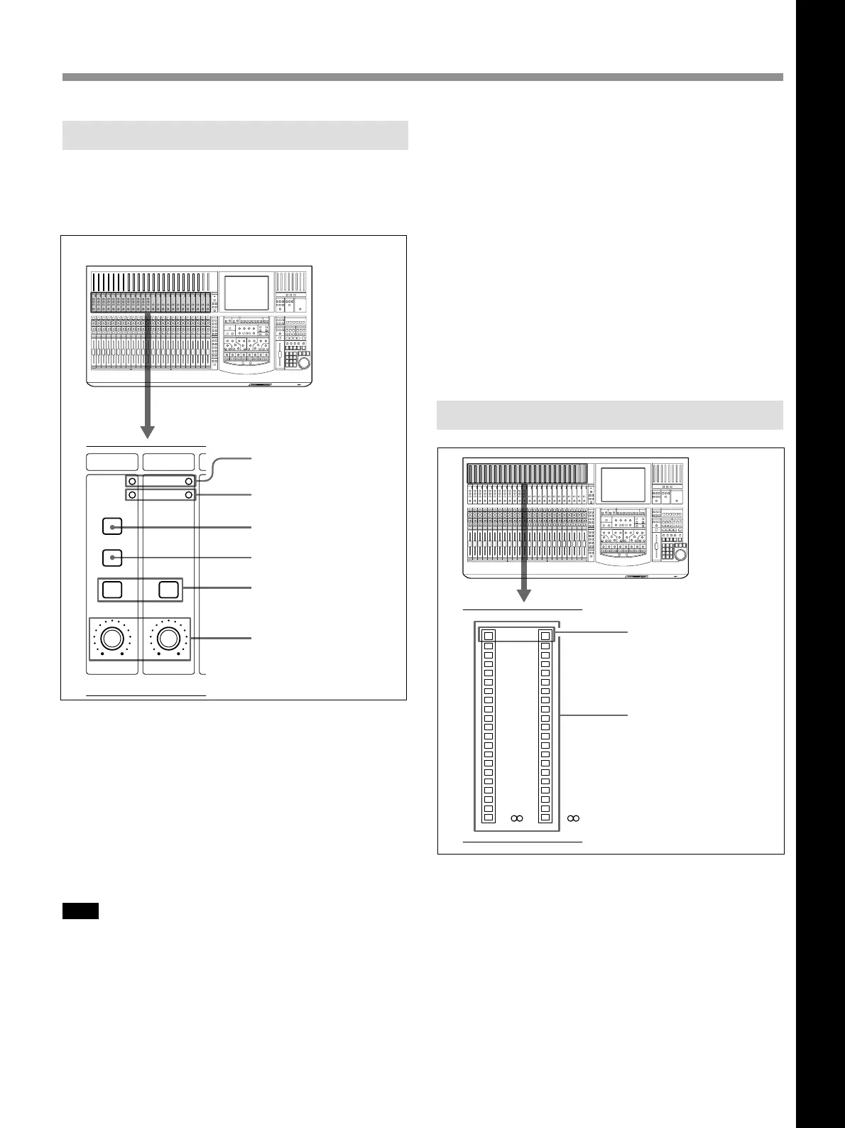
1 OVER (analog head amplifier peak) indicators
Lights when the input level reaches the level where the
analog head amplifier starts to clip. The clip level is
-6 dBFS.
2 SIGNAL (analog head amplifier signal)
indicators
Lights when the signal is input to the analog head
amplifier. The level at which the SIGNAL indicator
lights is about -40 dBFS.
Note
The OVER indicator and SIGNAL indicator are active
only when the input signal is routed to any channel
using the input router.
3 +48V button
Press this button to send + 48 V power to the
microphone connected to the IN A connector (XLR
connector) on the rear panel.
PA D
INPUT B
+48V
SIGNAL
GAIN
OVER
PA D
SIGNAL
GAIN
OVER
1 OVER indicators
2 SIGNAL indicators
3 +48V button
4 Input B button
5 PAD buttons
6 GAIN controls
4 Input B (input selector) button
Selects the input signal connected to the analog head
amplifier. When pressed, the IN-B connector (1/4”
TRS jack) on the rear panel becomes active. When this
button goes off, the IN A connector (XLR connector)
becomes active.
5 PAD buttons
When pressed, an attenuation pad of 30 dB is inserted
into the input circuit of the analog head amplifier.
6 GAIN controls
Adjusts the gain of the input circuit of the analog head
amplifier.
Channel Meter Panel
20
30
40
50
60
10
6
4
0
OVER
20
30
40
50
60
10
6
4
0
OVER
The channel meters indicate the input signal level of
the channel strips.
On the MISC SETUP window, you can select input,
pre-fader signal or post-fader signal to be metered.
When the input signal is the analog signal, these
meters indicate the level of the signal converted after
the A/D converter.
The OVER indicator lights when the level of the input
signal reaches the clip level.
Analog Head Amplifier Panel
This panel allows you to select the input circuit of the
analog input signal and their level adjustment.
Buttons and controls on this panel are not automatable.
OVER indicators
Channel meter
Chapter 2 Locations and Functions of Parts and Controls

 Loading...