– 31 –
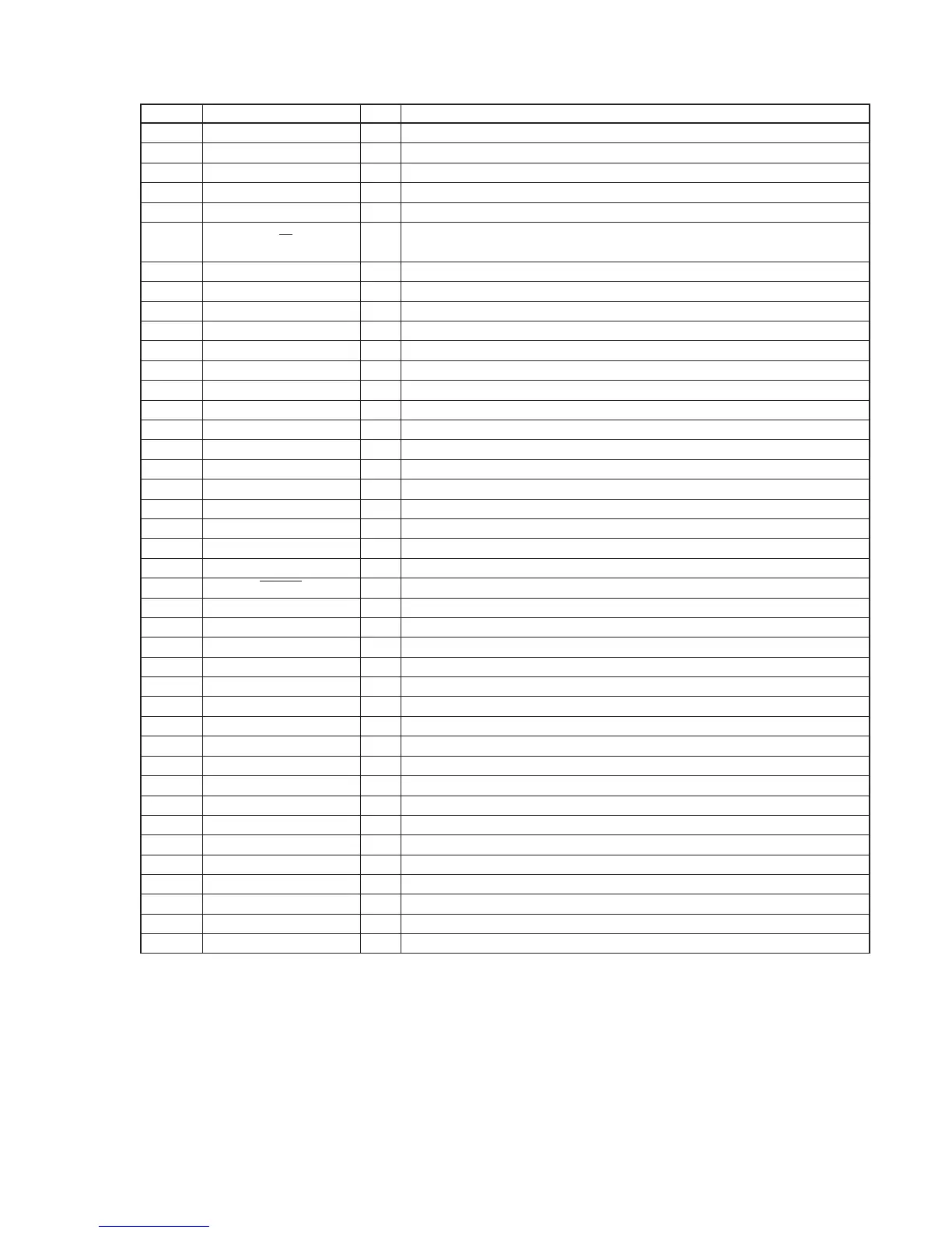
Pin No. Pin Name I/O Pin Description
57 GPIO1 — Not used. (open)
58 GPIO0 O General service programing signal output
59 V
DD
— Power supply pin (+3.3 V)
60 BYPASS — Not used. (Connect to ground.)
61 SPFRX I S/P DIF receive input port
62 P/M I
Resemblance input/output, resemblance port memory select signal input. Decide to
time of reset.
63 XTO — Not used. (open)
64 XTI I External system clock signal input
65 GND — Ground
66 SCKIN O Serial master clock signal output
67 V
DD
— Power supply pin (+3.3 V)
68 GND
A
— Analog ground
69 FLTAP I External filter capacitor connect pin
70 V
CCA
— Analog power supply pin (+3.3 V)
71 GND — Ground
72 CLKOUT — Not used. (open)
73, 74 D19, D18 — Not used. (open)
75 – 77 A17 – A19 — Not used. (open)
78 GND — Ground
79 SDC O Serial L/R surround data signal output
80 SDB O Serial L/R data signal output
81 V
DD
— Power supply pin (+3.3 V)
82 RESET I Reset signal input
83 SDA I Audio L/R data signal input
84 V
DD
— Power supply pin (+3.3 V)
85 SDE — Not used. (open)
86 TCK — Not used. (Connect to ground.)
87 SCK I Serial interface clock signal input
88 TBI — Not used. (Connect to ground.)
89 SI I Host serial interface data signal input
90 GND — Ground
91 SCKA O Serial clock data signal output
92 WSA O Word select, frame synchronize output port.
93 V
DD
— Power supply pin (+3.3 V)
94 SDF — Not used. (Connect to ground.)
95 WSB O Word select, frame synchronize output port.
96 D17 — Not used. (open)
97 SCKB O Serial clock data signal output
98 D16 — Not used. (open)
99 SPFTX/SDG — Not used. (Connect to ground.)
100 D15 — Not used. (open)