72
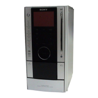
HCD-AZ2D/AZ5D
MAIN BOARD IC401 M30622MEP-A06FPU0 (SYSTEM CONTROLLER)
Pin No. Pin Name I/O Description
1 P_SM_DATA O Serial data output to the stream processor
2 P_SM_CLK O Serial data transfer clock signal output to the stream processor
3 ML9208 RESET O Reset signal output to the fluorescent indicator tube driver “L”: reset
4 SIRCS I Remote control signal input from the remote control receiver
5 ML9208 DATA O Serial data output to the fluorescent indicator tube driver
6 ML9208 CS O Chip select signal output to the fluorescent indicator tube driver
7 ML9208 CLK O Serial data transfer clock signal output to the fluorescent indicator tube driver
8 BYTE I External data bus line byte selection signal input terminal Fixed at “L” in this set
9 CN VSS – Ground terminal
10 XC-IN I Sub system clock input terminal (32.768 kHz)
11 XC-OUT O Sub system clock output terminal (32.768 kHz)
12 RESET I
System reset signal input terminal “L”: reset For several hundreds msec. after the
power supply rises, “L” is input, then it change to “H”
13 X-OUT O Main system clock output terminal (5 MHz)
14 VSS – Ground terminal
15 X-IN I Main system clock input terminal (5 MHz)
16 VCC – Power supply terminal (+3.3V)
17 NMI I Non-maskable interrupt input terminal Fixed at “H” in this set
18 USB_A_DET I USB memory detection signal input terminal Not used
19
P_DVD_I_ I
Disc slot in/out detection switch input terminal
MTK_SLOT_IN
20 AC-CUT I AC cut on/off detection signal input terminal “L”: AC cut on
21 TC A HALF I
Deck-A cassette detection signal input from the tape mechanism deck block “L”:
cassette in
22 TC A PLAY SW I
Deck-A playback detection signal input from the tape mechanism deck block “L”
playback
23 P_VIDEO_MUTE O Video muting on/off control signal output to the video amplifier “H”: muting on
24 BACKLIGHT O LED drive signal output for back light “H”: LED on
25 P_I_MREQ I Muting request signal input from the servo DSP
26 P_I_DVD_XIFCS I Chip select signal input from the servo DSP
27 P_I_KRMOD I Karaoke mode selection signal input from the servo DSP
28 P_O_DVD_BUSY O Busy signal output to the servo DSP
29 IIC-CLK O IIC data transfer clock signal output terminal Not used
30 IIC-DATA O IIC data output terminal Not used
31 P_O_DVD_SO O Serial data output to the servo DSP
32 P_I_DVD_SI I Serial data input from the servo DSP
33 PI_DVD_SCK O Serial data transfer clock signal output to the servo DSP
34 P_ID_IO_SYSRST O Reset signal output to the servo DSP “L”: reset
35 TC A CAPM O
Deck-A side capstan/reel motor drive signal output terminal “L”: FWD/stop, “H”:
REV
36 TC A TRG O Deck-A side trigger plunger drive signal output terminal “H”: plunger on
37 TUNED I Tuning detection signal input from the tuner unit “L”: tuned
38 ST-DOUT O PLL serial data output to the tuner unit
39 ST-CLK O PLL serial data transfer clock signal output to the tuner unit
40 ST-DIN I PLL serial data input from the tuner unit
41 ST-CE O PLL serial chip enable signal output to the tuner unit
42 P_LINK_LFE_SW O Audio signal (for sub woofer) selection signal output terminal (HCD-AZ5D only)
43 NO USE O Not used
44 P_TC_AMS_MUTE O Automatic music sensor muting on/off control signal output terminal “L”: muting on
w
w
w
.
x
i
a
o
y
u
1
6
3
.
c
o
m
Q
Q
3
7
6
3
1
5
1
5
0
9
9
2
8
9
4
2
9
8
T
E
L
1
3
9
4
2
2
9
6
5
1
3
9
9
2
8
9
4
2
9
8
0
5
1
5
1
3
6
7
3
Q
Q
TEL 13942296513 QQ 376315150 892498299
TEL 13942296513 QQ 376315150 892498299
http://www.xiaoyu163.com
http://www.xiaoyu163.com