13
Record Level (L)
Record Level (R)
RV101
RV201
IC306
40
49
3
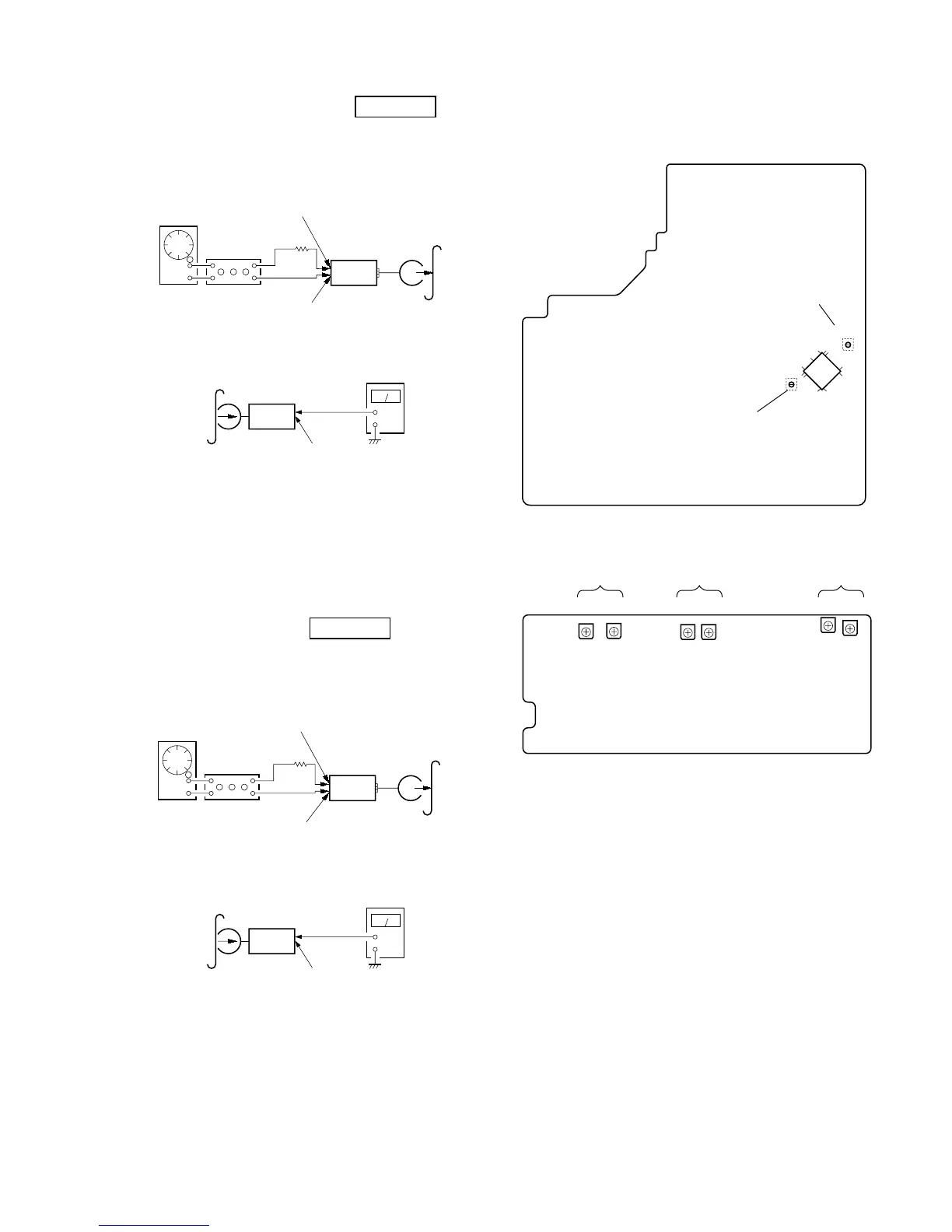
Record bias Current Adjustment
Procedure:
1. Mode: Record
2. Mode: Playback
Confirm playback the signal recorded in step 1 become adjustable
limits as follows.
If these levels do not adjustable limits, adjustment the RV403 (L-
CH) and RV423 (R-CH) on the TC board to repeat steps 1 and 2.
Adjustable limits: Playback output of 315 Hz to playback output
of 10 kHz: 0 ± 0.5 dB
Adjustment Location: TC and MAIN boards
Record Level Adjustment
Procedure:
1. Mode: Record
2. Mode: Playback
Confirm playback the signal recorded in step 1 become adjustable
limits as follows.
If these levels do not adjustable limits, adjustment the RV101 (L-
CH) and RV201 (R-CH) on the MAIN board to repeat steps 1 and
2.
Adjustable limits:
IC306 PB level: 36.7 to 41.1 mV (–26.5 to –25.5 dB)
Adjustment Location: MAIN board
DECK B
attenuator
set
Pin rd (L-CH) of IC306 on the MAIN board.
Pin th (R-CH) of IC306 on the MAIN board.
1) 315 Hz
2) 10 kHz
50 mV (–23.8 dB)
Pin rl (GND) of IC306 on the MAIN
board.
600 Ω
blank tape
CN-123
AF OSC
+
–
set
recorded
portion
IC306 (Pin r; : L-CH)
level meter
DECK B
set
Pin rd (L-CH) of IC306 on the MAIN board.
Pin
th (R-CH) of IC306 on the MAIN board.
315 Hz, 50 mV (–23.8 dB)
blank tape
CS-123
Pin
rl (GND) of IC306 on the MAIN board.
600 Ω
attenuator
AF OSC
+
–
set
recorded
portion
IC306 (Pin r; : L-CH)
level meter
Adjustment and Checking Location:
– MAIN BOARD (Conductor Side) –
– TC BOARD (Component Side) –
RV401 RV421 RV402 RV422
RV403
RV423
LL LRR R
Playback Level
(Deck-A)
Playback Level
(Deck-B)
Record Bias
Current