20
HCD-DZ100K/DZ500KF
Ver. 1.1
DVD SECTION
[TEST DISC LIST]
Use the following test disc on test mode.
• CD: YEDS-18 (PART No. 3-702-101-01)
or
PATD-012 (PART No. 4-225-203-01)
• DVD (SL) :
NTSC
HLX-503 (PART No. J-6090-069-A)
or
HLX-504 (PART No. J-6090-088-A)
PAL HLX-506 (PART No. J-6090-077-A)
• DVD (DL) :
NTSC
HLX-501 (PART No. J-6090-071-A)
or
HLX-505 (PART No. J-6090-089-A)
PAL HLX-507 (PART No. J-6090-089-A)
Note: Do not use exiting test disc for DVD.
Confirmation of mirror time adjustment and IOP adjustment (Refer
to page 24 of the TEST MODE)
[RFMON Level Check]
Connection:
Procedure:
1. Connect an oscilloscope to CN105 pin 6 (RFMON) and
CN105 pin 3 (GND) on the DMB10 board.
2. Turn the power on.
3. Set the test disc (DVD: HLX-503 (NTSC) or HLX-504 (PAL),
CD: YEDS-18) on the tray and press H button to playback.
4. Confirm that oscilloscope waveform is clear and check
RFMON signal level is correct or not.
Note: A clear RFMON signal waveform means that the shape “◊” can be
clearly distinguished at the center of the waveform.
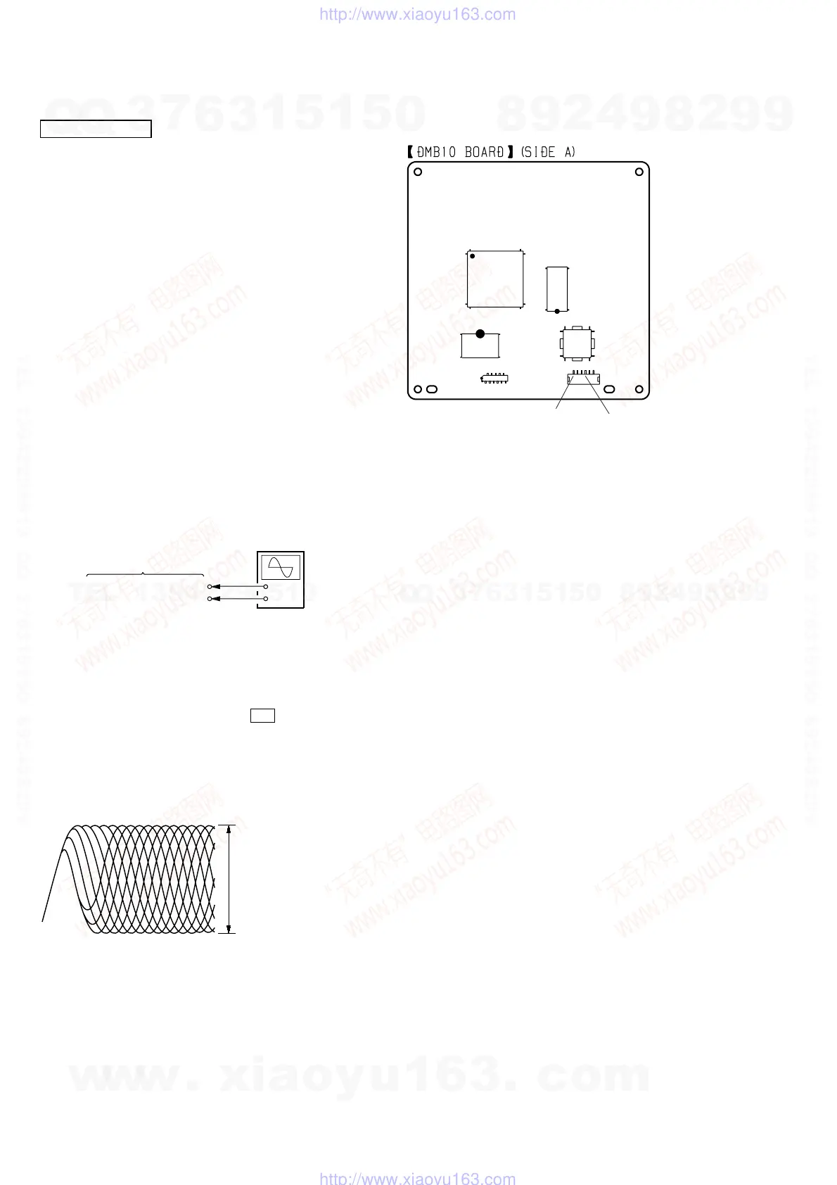
Checking Location: DMB10 board (Side A)
+
–
CN105 pin
6
(RFMON)
CN105 pin
3
(GND)
oscilloscope
DMB10 board
VOLT/DIV: 200 mV
TIME/DIV: 500 ns
RFMON signal waveform
level: 0.58 to 1.23 Vp-p (DVDSL)
0.57 to 1.1 Vp-p (CD)
IC102
IC101
IC104
IC201
CN105
CN106
CN105 pin
3
(GND
CN105 pin
6
(RFMON)
1
6
ELECTRICAL ADJUSTMENT
w
w
w
.
x
i
a
o
y
u
1
6
3
.
c
o
m
Q
Q
3
7
6
3
1
5
1
5
0
9
9
2
8
9
4
2
9
8
T
E
L
1
3
9
4
2
2
9
6
5
1
3
9
9
2
8
9
4
2
9
8
0
5
1
5
1
3
6
7
3
Q
Q
TEL 13942296513 QQ 376315150 892498299
TEL 13942296513 QQ 376315150 892498299
http://www.xiaoyu163.com
http://www.xiaoyu163.com