EasyManua.ls Logo

Sony HCD-EP313 User Manual

Sony HCD-EP313
44 pages
To Next Page IconTo Next Page
Page #1 background imageLoading...
Page #1 background image
HCD-EP313
US Model
Canadian Model
AEP Model
UK Model
SERVICE MANUAL
MICRO HI-FI COMPONENT SYSTEM
Sony Corporation
Home Audio Company
Published by Sony Engineering Corporation
9-877-237-01
2003D167800-1
© 2003.04
HCD-EP313 is the Amplifier, CD player, Tape
Deck and Tuner section in CMT-EP313.
SPECIFICATIONS
Ver 1.0 2003. 04
Model Name Using Similar Mechanism NEW
CD
CD Mechanism Type KSM-213EDP
Section
Base Unit Name BU-K7BD44B
Optical Pick-up Name KSS-213E/C2N
TAPE
Model Name Using Similar Mechanism NEW
Section
Tape Transport Mechanism Type ADR2080FR4
— Continued on next page —
Amplifier section
AUDIO POWER SPECIFICATIONS:
(U.S.A. model only)
POWER OUTPUT AND TOTAL HARMONIC
DISTORTION:
With 6-ohm loads, both channels driven, from 120 -
10,000 Hz; rated 10 watts per channel minimum RMS
power, with no more than 10% total harmonic
distortion from 250 milliwatts to rated output.
North American model:
Continuous RMS power output (reference):
10 + 10 W
(6 ohms at 1 kHz, 10%
THD)
European model:
DIN power output (rated): 7 + 7 W
(6 ohms at 1 kHz, DIN)
Continuous RMS power output (reference):
10 + 10 W
(6 ohms at 1 kHz, 10%
THD)
Music power output (reference):
20 + 20 W
Other models:
The following measured at AC 230 V or AC 120 V, 50/
60 Hz
DIN power output (rated): 7 + 7 W
(6 ohms at 1 kHz, DIN)
Continuous RMS power output (reference):
10 + 10 W
(6 ohms at 1 kHz, 10%
THD)
Inputs
MD IN (phono jacks):
Sensitivity 500 mV,
impedance 47 kilohms
Outputs
PHONES (stereo minijack):
Accepts headphones with
an impedance of 8 ohms or
more
SPEAKER: Accepts impedance of 6 to
16 ohms.
CD player section
System Compact disc and digital
audio system
LaserSemiconductor laser
(
λ
=780 nm)
Emission duration:
continuous
Frequency response 2 Hz – 20 kHz (±0.5 dB)
Tape deck section
Recording system 4-track 2-channel stereo
Frequency response 50 – 13,000 Hz (±3 dB),
using Sony TYPE I
cassettes
Tuner section
FM stereo, FM/AM superheterodyne tuner
FM tuner section
Tuning range 87.5 – 108.0 MHz (50-kHz
step)
Antenna FM lead antenna
Antenna terminals 75 ohms balanced
Intermediate frequency 10.7 MHz
AM tuner section
Tuning range
Pan-American model: 530 – 1,710 kHz
(with the tuning interval
set at 10 kHz)
531 – 1,710 kHz
(with the tuning interval
set at 9 kHz)
European model: 531 – 1,602 kHz
(with the tuning interval
set at 9 kHz)
Other models: 530 – 1,710 kHz
(with the tuning interval
set at 10 kHz)
531 – 1,602 kHz
(with the tuning interval
set at 9 kHz)
Antenna AM loop antenna, external
antenna terminal
Intermediate frequency 450 kHz
Question and Answer IconNeed help?

Do you have a question about the Sony HCD-EP313 and is the answer not in the manual?

Sony HCD-EP313 Specifications

General IconGeneral
Disc PlayerCD Player
Remote ControlYes
CD PlayerYes
USB PortNo
TypeMini System
Tuner BandsAM/FM

Summary

SPECIFICATIONS

SERVICING NOTES

Servicing Precautions and Checks

Procedures for safe repair, including handling sensitive components and AC leakage testing.

GENERAL

Button Locations and Reference Pages

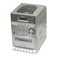
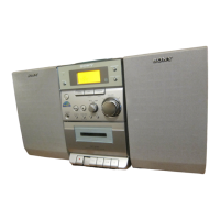
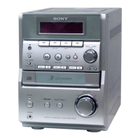
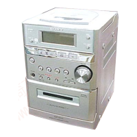
Guide to locating buttons and parts on the main unit and remote control.

DISASSEMBLY

Rear Cabinet

Step-by-step instructions for disassembling the rear cabinet.

CD Cabinet Section

Instructions for disassembling the CD cabinet section.

Front Panel Section

Instructions for disassembling the front panel section.

CONTROL Board, BACK LIGHT Board

Instructions for disassembling the control and back light boards.

Tape Mechanism Deck

Instructions for disassembling the tape mechanism deck.

Cassette Door Assy

Instructions for disassembling the cassette door assembly.

MAIN Board, POWER Board

Instructions for disassembling the main and power boards.

CD Mechanism Deck (KSM-213EDP)

Instructions for disassembling the CD mechanism deck.

Optical Pick-up (KSS-213E/C2N)

Instructions for disassembling the optical pick-up.

MECHANICAL ADJUSTMENTS

Torque Measurement

Specifications and methods for measuring torque for various mechanical adjustments.

ELECTRICAL ADJUSTMENTS

Deck Section Adjustments

Procedures for adjusting tape deck performance, including azimuth and speed.

CD SECTION

CD Section Performance Checks

Procedures for checking CD performance, including S-curve, RFAC, and RFDC levels.

E-F Balance Check

Procedure for checking the E-F balance of the CD servo system.

DIAGRAMS

Circuit Boards Location

Diagram showing the physical location of circuit boards within the unit.

Block Diagram

Overall system block diagram illustrating component interconnections.

Printed Wiring Board - CD Section

Component layout diagram for the CD section printed wiring board.

Schematic Diagram - CD Section

Circuit schematic diagram for the CD section.

Printed Wiring Board - MAIN Section (COMPONENT SIDE)

Component layout diagram for the MAIN board (component side).

Printed Wiring Board - MAIN Section (CONDUCTOR SIDE)

Component layout diagram for the MAIN board (conductor side).

Schematic Diagram – MAIN Section

Circuit schematic diagram for the MAIN section.

Printed Wiring Board – CONTROL Section (COMPONENT SIDE)

Component layout diagram for the CONTROL board (component side).

Printed Wiring Board – CONTROL Section (CONDUCTOR SIDE)

Component layout diagram for the CONTROL board (conductor side).

Schematic Diagram – CONTROL Section

Circuit schematic diagram for the CONTROL section.

Printed Wiring Board – POWER Section

Component layout diagram for the POWER section.

Schematic Diagram – POWER Section

Circuit schematic diagram for the POWER section.

IC Block Diagrams - CD Board

Internal block diagrams for key ICs in the CD section.

IC Pin Function Description

Detailed description of IC pin functions for the system controller.

EXPLODED VIEWS

Overall Section Exploded View

Exploded view showing the overall assembly of the unit.

Front Panel Section Exploded View

Exploded view of the front panel components.

CD Cabinet Section Exploded View

Exploded view of the CD cabinet section components.

Optical Pick-up Block Exploded View

Exploded view of the optical pick-up block.

ELECTRICAL PARTS LIST

REVISION HISTORY

Related product manuals