63
HCD-GNX780/GNX880
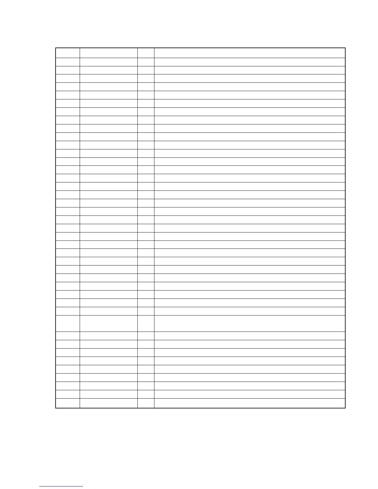
Pin No. Pin Name I/O Description
1 to 8 G8 to G1 O FLD grid signal output
9, 10 P1,P2 O FLD segment signal output
11 VSS-IO – Ground terminal
12 to 22 P3 to P13 O FLD segment signal output
23 VDD-FIP – Power supply terminal(+3.3V)
24 to 41 P14 to P31 O FLD segment signal output
42 VSS-IO – Ground terminal
43 to 47 P32 to P36 O FLD segment signal output
48 VKK – Power supply terminal (-35V)
49 MD0 I Micom operating mode (Pull up)
50 MD1/VDD-VFT I Micom operating mode (Pull up)
51 MD2 I Micom operating mode (Pull down)
52 LED-CD/DVD,TUNER O LED drive signal output
53 LED-TAPE,TV/SAT O LED drive signal output
54
LED-VIDEO (PAUSE,STOP)
O LED drive signal output
55
LED-(AMS+,AMS-),(FF,FR)
O LED drive signal output
56 LED-VOLUME 1,2 O LED drive signal output
57 LED-VOLUME 3,4 O LED drive signal output
58 LED-VOLUME 5,6 O LED drive signal output
59 LED-VOLUME 7,8 O LED drive signal output
60 IIC DATA I/O IIC bus serial data input/output
61 IIC CLOCK I/O IIC bus serial clock input/output
62 AVCC – Power supply terminal (+3.3V)
63 AVSS – Ground terminal
64 to 66 KEY0 to KEY2 I Key input (A/D)
67 ALL BAND I Audio L+R signal input
68 to 71 BPF4 to BPF1 I Spectrum analyzer signal input
72 OPERATION DIAL I OPERATION DIAL encoder signal input
73 JOG X-ROUND I X-ROUND JOG encoder signal input (Not used)
74 VOLUME I Volume encoder signal input
75
LED-(BEAT JUMP,BEAT MAX)
O LED drive signal output (Not used)
76
LED-(BALANCE,WAVE,
O LED drive signal output (Not used)
FADER,RANDOM),DELAY
77 RESET I Reset signal input
78 LED-FLANGER,CHORUS O LED drive signal output
79 LED-PLAY O LED drive signal output
80 LED-SELECTOR O LED group select signal output
81 VSS-CPU – Ground terminal
82 XOUT O Crystal oscillator output (4MHz)
83 XIN I Crystal oscillator input (4MHz)
84 VCC-CPU – Power supply terminal (+3.3V)
85 to 100 G24 to G9 O FLD grid signal output
• IC902 MB90M407PF-G-148E1 DISPLAY CONTROL (PANEL BOARD)
 Loading...