– 69 –
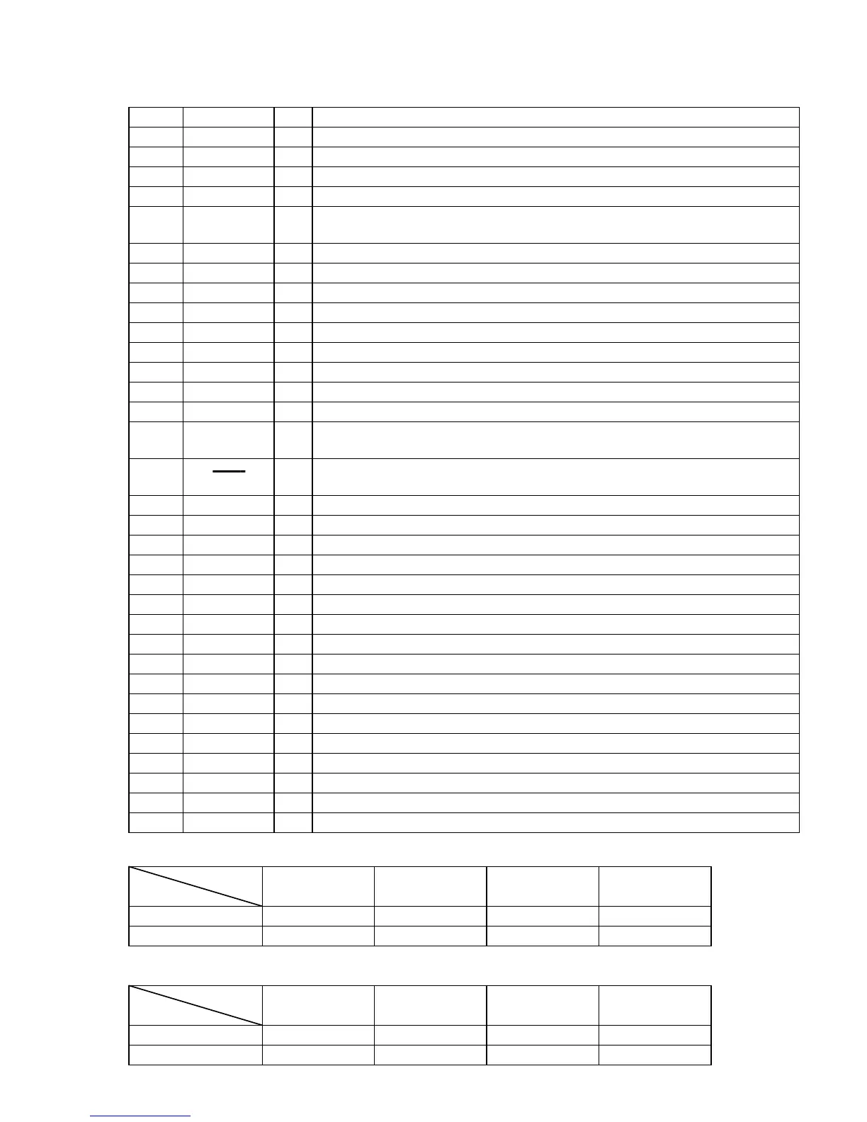
Pin No. Pin Name I/O Function
42 PL-LATCH O
Serial data latch pulse output terminal Not used (open)
43 COM-DIN I
Serial data input terminal Not used (fixed at “L”)
44 COM-DOUT O
Serial data output terminal Not used (open)
45 COM-CLK O
Serial data transfer clock signal output terminal Not used (open)
46 CD-POWER O
Power on/off control signal output for the CD mechanism deck section
“H”: power on, “L”: standby
47 CD-DATA O
Serial data output to the CXD2519Q (IC103)
48 CD-CLK O
Serial data transfer clock signal output to the CXD2519Q (IC103)
49 PL-CLK O
Serial data transfer clock signal output terminal Not used (open)
50 PL-DATA O
Serial data output terminal Not used (open)
51 M62442-CLK O
Serial data transfer clock signal output to the M62442FP (IC101)
52 M62442-DATA O
Serial data output to the M62442FP (IC101)
53
LEVEL-CONT-A
O
Level control signal output terminal Not used (open)
54
LEVEL-CONT-B
O
Level control signal output terminal Not used (open)
55 IIC-DATA I/O
Communication data bus with the fluorescent indicator tube driver (IC601)
56 IIC-CLK I/O
Communication data reading clock signal input or transfer clock signal output with the fluo-
rescent indicator tube driver (IC601)
57 XRST O
Reset signal output to the CXA1992AR (IC101), BA5941FP (IC102) and CXD2519Q (IC103) on
the CD mechanism deck section “L”: reset
58 XLT O
Serial data latch pulse output to the CXD2519Q (IC103)
59 FOCUS-SW O
Focus control signal output terminal Not used (open)
60 TBL-L O
Motor drive signal output to the disc tray turn motor driver (IC701) *1
61 TBL-R O
Motor drive signal output to the disc tray turn motor driver (IC701) *1
62 NCO O
Not used (open)
63 LOAD-OUT O
Motor drive signal output to the disc tray slide motor driver (IC801) *2
64 LOAD-IN O
Motor drive signal output to the disc tray slide motor driver (IC801) *2
65 ST-CLK O
PLL serial data transfer clock signal output to the FM/AM tuner unit
66 ST-DIN I
PLL serial data input from the FM/AM tuner unit
67 ST-DOUT O
PLL serial data output to the FM/AM tuner unit
68 ST-CE O
PLL chip enable signal output to the FM/AM tuner unit
69 TUNED I
Tuning detection signal input from the FM/AM tuner unit “L”: tuned
70 STEREO I
FM stereo detection signal input from the FM/AM tuner unit “L”: stereo
71 VSS —
Ground terminal
72 ST-MUTE O
Tuner muting control signal output to the FM/AM tuner unit “L”: muting on
73 SENS2 I
Internal status (SENSE) signal input from the CXA1992AR (IC101)
74 SENS I
Internal status (SENSE) signal input from the CXD2519Q (IC103)
*2 Disc tray slide motor (M801) control
LOAD-OUT (pin ^£)
“H” “H” “L” “L”
LOAD-IN (pin ^¢)
“H” “L” “H” “L”
Terminal
STOP TABLE IN TABLE OUT BRAKE
Mode
*1 Disc tray turn motor (M701) control
TB-L (pin ^º)
“H” “L” “H” “L”
TB-R (pin ^¡)
“H” “H” “L” “L”
Terminal
STOP
COUNTER-
CLOCKWISE
CLOCKWISE BRAKE
Mode