50
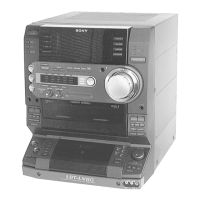
HCD-L1
Pin No.
51
52
53
54
55
56,57
58
59
60-67
68
69-73
74
75
76
77
78
79,80
81
82
83
84
85,86
87
88
89,90
91
92
93
94-96
97
98
99
100
I/O
O
O
O
O
O
O
—
—
O
O
O
—
—
I
I
I
I
I
I
I
I
I
I
I
I
I
O
I
O
O
I
O
O
Pin Name
D.SENS.OUT
LOD1POS
LOD1NEG
LOD2POS
LOD2NEG
—
BVDD
BVSS
—
CHECK
—
AVDD
AVSS
AVREF
OPTSNS1
OPTSNS2
—
SEL0
SEL1
SEL2
SEL3
—
MECHA—JIG
ADJ
IICHELP
SCOR
—
AC—CUT
—
—
—
—
DACLAT
Description
D sensor output
Loading motor output (+)
Loading motor output (-)
Chucking motor output (+)
Chucking motor output (-)
Not used
+5 V power terminal
Ground terminal
Not used
Check terminal
Not used
+5 V power terminal
Analog ground terminal
Analog reference voltage
D sensor input
L sensor input
Not used
Destination select input (Overseas: H, Japan: L)
Model select input (SL7: H, SL1: L) Fixing L
Model select input (not used) Fixing L
BD JIG select input (Normal: H, BD only: L) Fixing H
Not used
MECHA JIG (fixing L)
Adjustment mode input (fixing H)
1
2
C bus help input
CXD3068 SUBQ SYNC input
Not used
AC off input
Not used
Flash ROM data output
Flash ROM data input
Flash ROM clock output
DAC latch output