14
3.04 – 6.96 N • m
(31 to 71 g • cm)
(0.43 – 0.98 oz • inch)
0.20 – 0.58 N • m
(2 to 6 g • cm)
(0.02 – 0.08 oz • inch)
3.04 – 6.96 N • m
(31 to 71 g • cm)
(0.43 – 0.98 oz • inch)
0.20 – 0.58 N • m
(2 to 6 g • cm)
(0.02 – 0.08 oz • inch)
6.97 – 14.02 N • m
(71 to 143 g • cm)
(0.98 – 1.99 oz • inch)
0.98 N • m or more
(100 g or more)
(3.53 oz or more)
0.98 N • m or more
(100 g or more)
(3.53 oz or more)
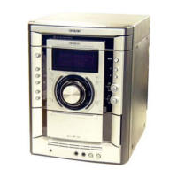
CQ-102C
CQ-102C
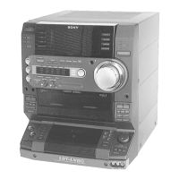
CQ-102RC
CQ-102RC
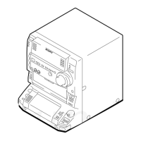
CQ-201B
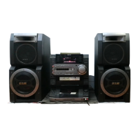
CQ-403A
CQ-403R
Precaution
1. Clean the following parts with a denatured alcohol-moistened
swab:
record/playback heads pinch rollers
erase head rubber belts
capstan idlers
2. Demagnetize the record/playback head with a head demagne-
tizer.
3. Do not use a magnetized screwdriver for the adjustments.
4. After the adjustments, apply suitable locking compound to the
parts adjusted.
5. The adjustments should be performed with the rated power sup-
ply voltage unless otherwise noted.
Torque Measurement
Record/Playback Head Azimuth Adjustment
(Deck A, Deck B)
Note: Perform this adjustments for both decks.
Procedure:
1. Mode : Playback
Signal
Used forTape
SECTION 4
MECHANICAL ADJUSTMENTS
Mode
FWD
FWD
back tension
REV
REV
back tension
FF/REW
FWD tension
REV tension
Torque meter
Meter reading
SECTION 5
ELECTRICAL ADJUSTMENTS
DECK SECTION 0 dB=0.775V
1. Demagnetize the record/playback head with a head demagnetizer.
2. Do not use a magnetized screwdriver for the adjustments.
3. After the adjustments, apply suitable locking compound to the
parts adjusted.
4. The adjustments should be performed with the rated power sup-
ply voltage unless otherwise noted.
5. The adjustments should be performed in the order given in this
service manual. (As a general rule, playback circuit adjustment
should be completed before performing recording circuit adjust-
ment.)
6. The adjustments should be performed for both L-CH and R-CH.
7. Switches and controls should be set as follows unless otherwise
specified.
P-4-A100
WS-48B
P-4-L300
10 kHz, –10 dB
3 kHz, 0 dB
315 Hz, 0 dB
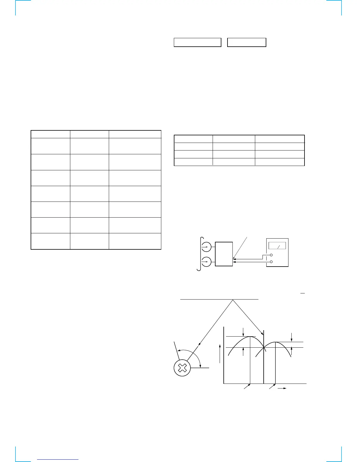
Azimuth Adjustment
Tape Speed Adjustment
Level Adjustment
2. Turn the adjustment screw and check output peaks. If the peaks
do not match for L-CH and R-CH, turn the adjustment screw so
that outputs match within 1 dB of peak.
test tape
P-4-A100
(10kHz, –10dB)
MD OUT
level meter
set
+
–
L-CH
peak
R-CH
peak
screw
position
output
level
within
1 dB
L-CH
peak
R-CH
peak
screw
position
within 1dB
 Loading...