– 36 –
4. After the adjustments, apply suitable locking compound to the
parts adjusted.
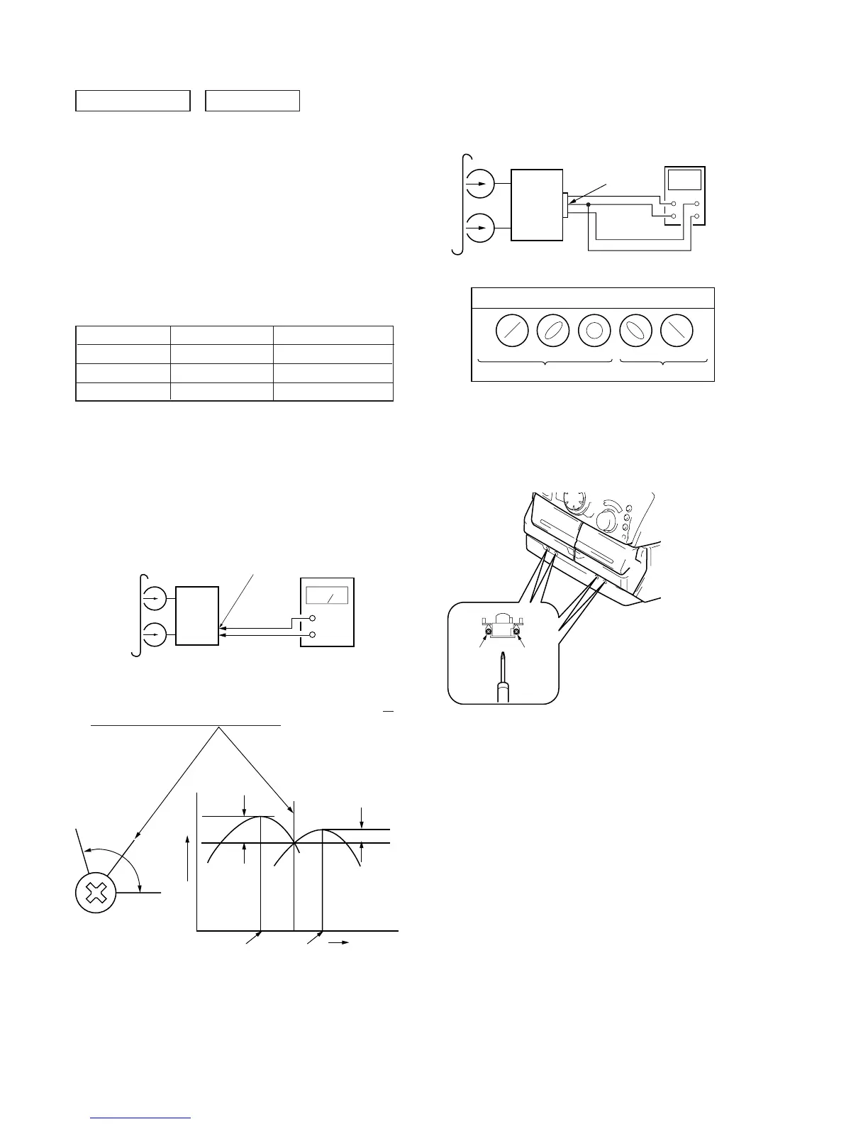
Adjustment Location: Playback Head (Deck A)
Record/Playback/Erase Head (Deck B)
3. Mode: Playback
test tape
P-4-A100
(10kHz, –10dB)
oscilloscope
set
Waveform of oscilloscope
in phase 45
°
90
°
135
°
180
°
good
wrong
VIDEO (AUDIO) OUT
Reverse Foward
Record/Playback Head Azimuth Adjustment
(Deck A, Deck B)
Note: Perform this adjustments for both decks.
Procedure:
1. Mode : Playback
Signal
Used for
Tape
DECK SECTION 0 dB=0.775V
1. Demagnetize the record/playback head with a head damagnetizer.
2. Do not use a magnetized screwdriver for the adjustments.
3. After the adjustments, apply suitable locking compound to the
parts adjusted.
4. The adjustments should be performed with the rated power sup-
ply voltage unless otherwise noted.
5. The adjustments should be performed in the order given in this
service manual. (As a general rule, playback circuit adjustment
should be completed before performing recording circuit adjust-
ment.)
6. The adjustments should be performed for both L-CH and R-CH.
7. Switches and controls should be set as follows unless otherwise
specified.
P-4-A100
WS-48B
P-4-L300
10 kHz, –10 dB
3 kHz, 0 dB
315 Hz, 0 dB
Azimuth Adjustment
Tape Speed Adjustment
Level Adjustment
2. Turn the adjustment screw and check output peaks. If the peaks
do not match for L-CH and R-CH, turn the adjustment screw so
that outputs match within 1 dB of peak.
test tape
P-4-A100
(10kHz, –10dB)
VIDEO (AUDIO) OUT
level meter
set
+
–
L-CH
peak
R-CH
peak
screw
position
output
level
within
1 dB
L-CH
peak
R-CH
peak
screw
position
within 1dB