– 37 –
Tape Speed Adjustment (Deck A)
Note: Set the test mode using the following method and begin tape
speed adjustment.
In the test mode, the speed will switch to double speed or
normal speed each time the HI DUB button is pressed.
Procedure:
With the power turned ON, press the p button, ENTER/NEXT
button, and DISC 3 button simultaneously.
(The “CD TYPE INDICATOR” on the fluorescent display tube will
blink while in the test mode.)
To exit the test mode, press the 1/u button.
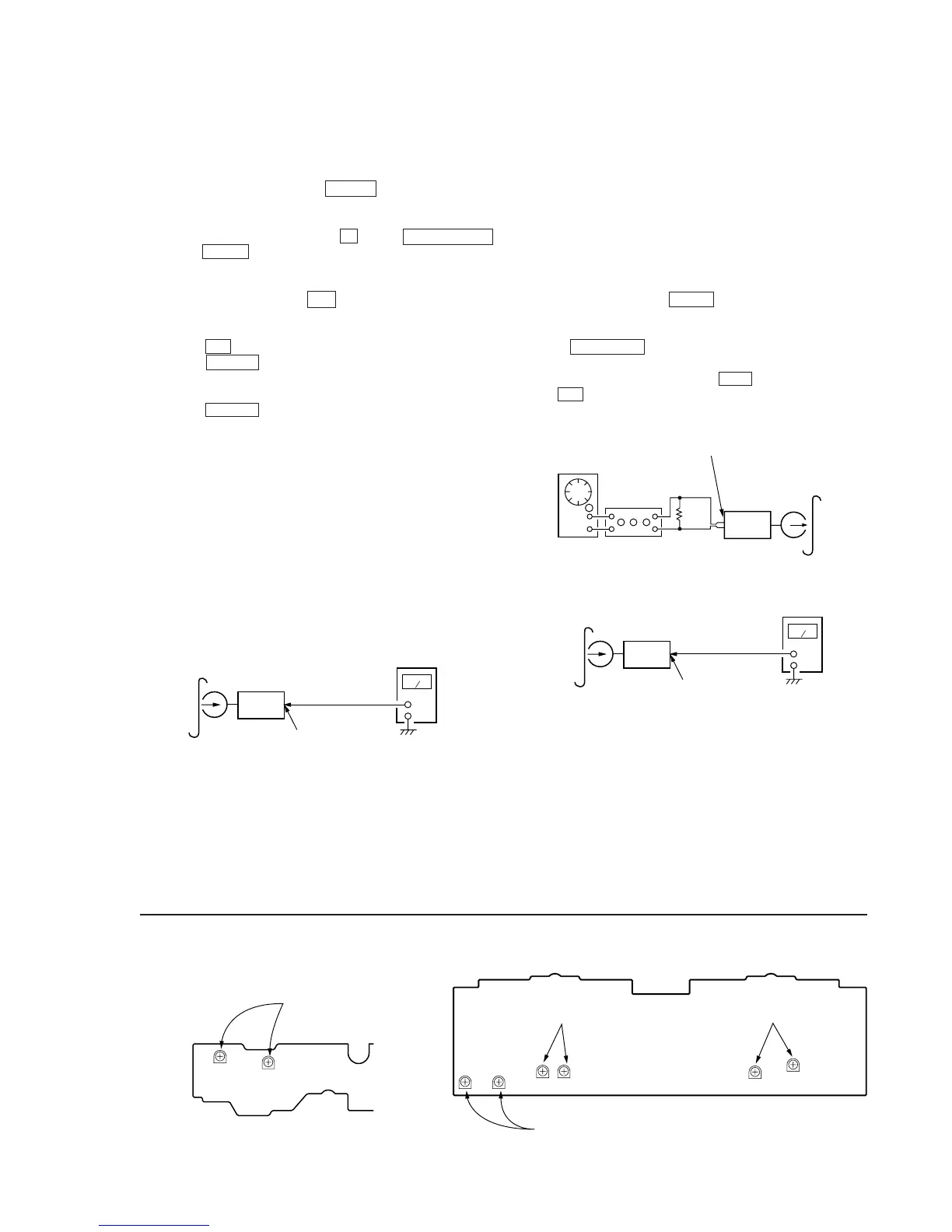
1. Insert the WS-48B into deck B.
2. Press the ( button of deck B.
3. Press the HI DUB button and play the tape at double speed.
4. Adjust RV1001 of the LEAF SW board so that the reading of
the frequency counter becomes 6000 ± 180 Hz.
5. Press the HI DUB button and play the tape at normal speed.
6. Adjust RV1002 of the LEAF SW board so that the reading of
the frequency counter becomes 3000 ± 90 Hz.
Adjustment Location: LEAF SW board
Sample Value of Wow and flutter
W.RMS (JIS) less than 0.3%
(test tape: WS-48B)
Playback Level Adjustment (Deck A, Deck B)
Procedure:
Mode: Playback
Deck A is RV311 (L-CH) and RV411 (R-CH), deck B is RV301
(L-CH) and RV401 (R-CH)
so that adjustment within the following adjustment level.
Adjustment level:
CN301 playback level: 301.5 to 338.3 mV (–8.2 to –7.2 dB)
level difference between the channels: within ± 0.5 dB
Adjustment Location: AUDIO board
Adjustment Location
[LEAF SW BOARD]
test tape
P-4-L300
(315Hz, 0dB)
level meter
set
VIDEO (AUDIO) OUT
RV1002 RV1001
RV1002(Normal Speed
RV1001(High Speed)
Record Bias Adjustment (Deck B)
Procedure:
INTRODUCTION
When set to the test mode performed in Tape Speed Adjust-
ment, when the tape is rewound after recording, the “REC memory
mode” which rewinds only the recorded portion and playback is
set.
This “REC memory mode” is convenient for performing this ad-
justment. During recording, the input signal FUNCTION will auto-
matically switch to VIDEO.
(After recording, press the – 0 button without stopping will
return to the position where recording was started.)
1. Press FUNCTION button to select VIDEO. (This step is not
necessary if the above test mode has already been set.)
2. Insert a tape into deck B, press the REC button, and then press
the ( button to start recording.
3. Mode: Record
5. Confirm playback the signal recorded in step 2 become adjust-
ment level as follows.
If these levels do not adjustment level, adjust the RV341 (L-
CH) and RV441 (R-CH) on the AUDIO board to repeat steps 3
and 4.
Adjustment level: The playback output of 10 kHz level difference
against 315 Hz reference should be ± 1.0 dB.
Adjustment Location: AUDIO board
4. Mode: Playback
recorded
position
level meter
set
VIDEO (AUDIO) OUT