– 34 –
TUNER SECTION 0dB=1µV
Note: As a front-end (FE1) is difficult to repair if faulty, replace it
with new one.
AM Section Adjustment
Setting:
AM Tuned Level Adjustment
Band: AM or MW
Procedure:
1. Set the output of SSG so that the input level of the set becomes
55 dB.
2. Tune the set to 1,050 kHz (US, CND models), 999 kHz (other
models).
3. Adjust RV41 (AEP, UK models), RV42 (other models) to the
point (moment) when the TUNED indicator will change from
going off to going on.
Adjustment Location : TCB board
FM Section Adjustment
Note: This adjustment should be performed after the AM Tuned
Level Adjustment due to the same adjustment element.
Setting:
Adjustment Location:
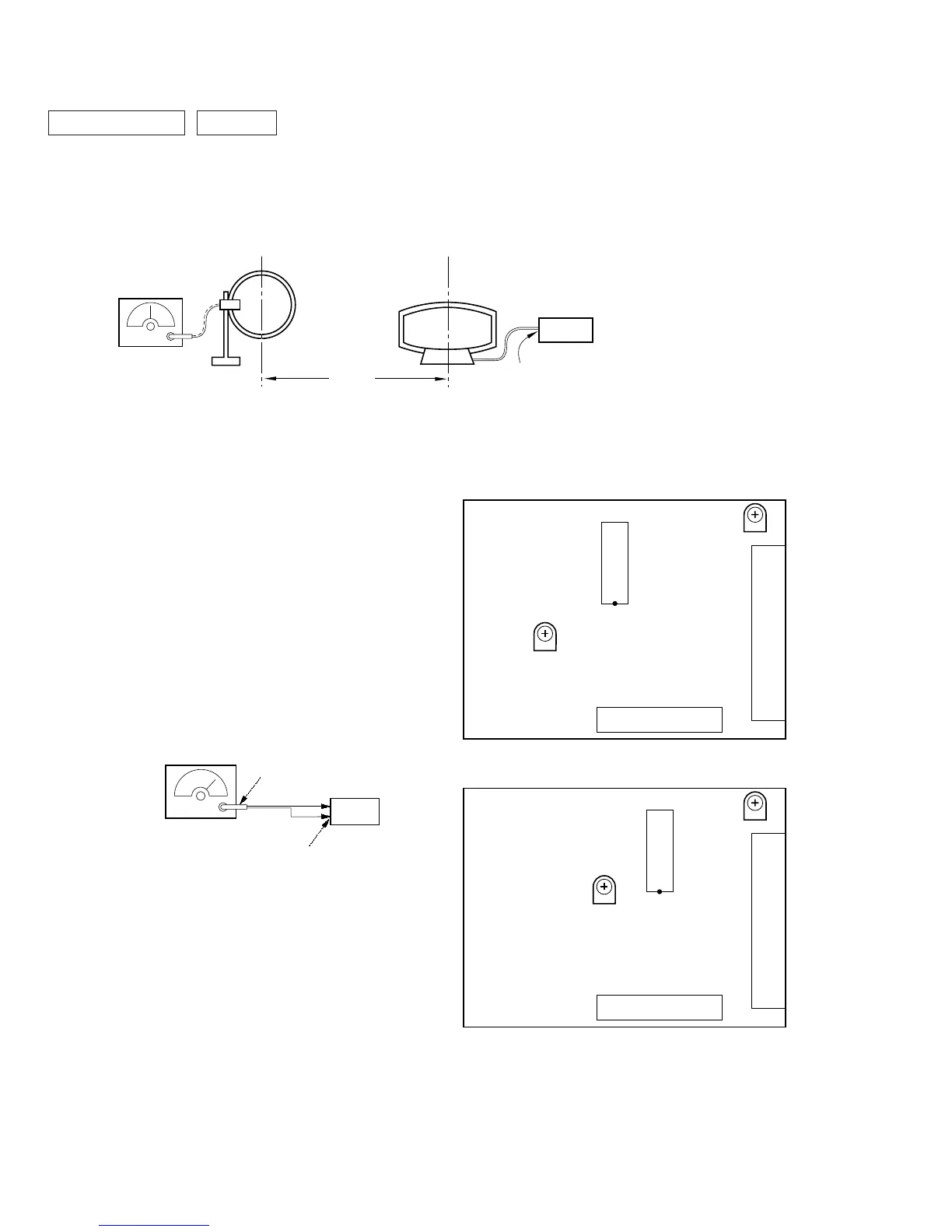
AEP, UK model
[TCB BOARD] (Component Side)
RV42
IC41
RV41
TM1
FE1
Other model
[TCB BOARD] (Component Side)
RV41
IC2
RV42
TM1
FE1
• Abbreviation
CND: Canadian model
AM RF SSG
loop antenna
set
loop antenna
(Supplied accessories)
60 cm
AM ANTENNA
terminal (TM1)
30% amplitude
modulation by
400 Hz signal
Field strength dB (
µ
V/m) =SSG output level dB (
µ
V/m) –26 dB.
Carrier frequency : 98 MHz
Modulation : AUDIO 1 kH, 75 kHz
deviation (100%)
FM ANTENNA terminal
(TM1) (75
Ω
open)
75
Ω
coaxial
set
FM RF stereo signal
generator
FM Tuned Level Adjustment
Band: FM
Procedure:
1. Supply a 25dBµ 98 MHz signal from the ANTENNA terminal.
2. Tune the set to 98 MHz.
3. If the TUNED indicator does not light, adjust RV42 (AEP, UK
models), RV41 (other models) to the point (moment) when the
TUNED indicator will change from going off to going on.
Adjustment Location: TCB board