– 4 –
TABLE OF CONTENTS
1. GENERAL
Getting Started .................................................................. 5
Basic Operations............................................................... 8
The CD Player .................................................................. 12
The Tape Deck .................................................................. 14
DJ Effects ......................................................................... 15
Sound Adjustment ............................................................ 16
Other Features .................................................................. 18
2. DISASSEMBLY........................................................... 21
3. TEST MODE ................................................................ 29
4. MECHANICAL ADJUSTMENTS.......................... 31
5. ELECTRICAL ADJUSTMENTS
DECK Section .................................................................. 31
Tuner Section .................................................................... 34
CD Section........................................................................ 35
6. DIAGRAMS
6-1. Block Diagrams
Tuner Section .................................................................... 39
CD Section........................................................................ 40
Main Section..................................................................... 41
6-2. Schematic Diagram – BD Section – ................................. 43
6-3. Printed Wiring Board – BD Section – .............................. 45
6-4. Schematic Diagram – CD Motor Section – ..................... 47
6-5. Printed Wiring Boards – CD Motor Section –................. 49
6-6. Schematic Diagram – Tuner Section – ............................ 51
6-7. Printed Wiring Board – Tuner Section – ......................... 53
6-8. Printed Wiring Boards – Deck Section –......................... 55
6-9. Schematic Diagram – Deck Section – ............................. 57
6-10. Schematic Diagram – Main Section – ............................. 61
6-11. Printed Wiring board – Main Section – ........................... 65
6-12. Schematic Diagrm – Panel Section – ............................... 68
6-13. Printed Wiring Boards – Panel Section – ......................... 71
6-14. Printed Wiring Boards – Power Section – ........................ 75
6-15. Schematic Diagram – Power Section – ............................ 77
6-16. IC Pin Function Description ............................................. 82
7. EXPLODED VIEWS .................................................. 86
8. ELECTRICAL PARTS LIST ................................... 95
SERVICING NOTES
NOTES ON HANDLING THE OPTICAL PICK-UP
BLOCK OR BASE UNIT
The laser diode in the optical pick-up block may suffer electrostatic
break-down because of the potential difference generated by the
charged electrostatic load, etc. on clothing and the human body.
During repair, pay attention to electrostatic break-down and also
use the procedure in the printed matter which is included in the
repair parts.
The flexible board is easily damaged and should be handled with
care.
NOTES ON LASER DIODE EMISSION CHECK
The laser beam on this model is concentrated so as to be focused on
the disc reflective surface by the objective lens in the optical pick-
up block. Therefore, when checking the laser diode emission, ob-
serve from more than 30 cm away from the objective lens.
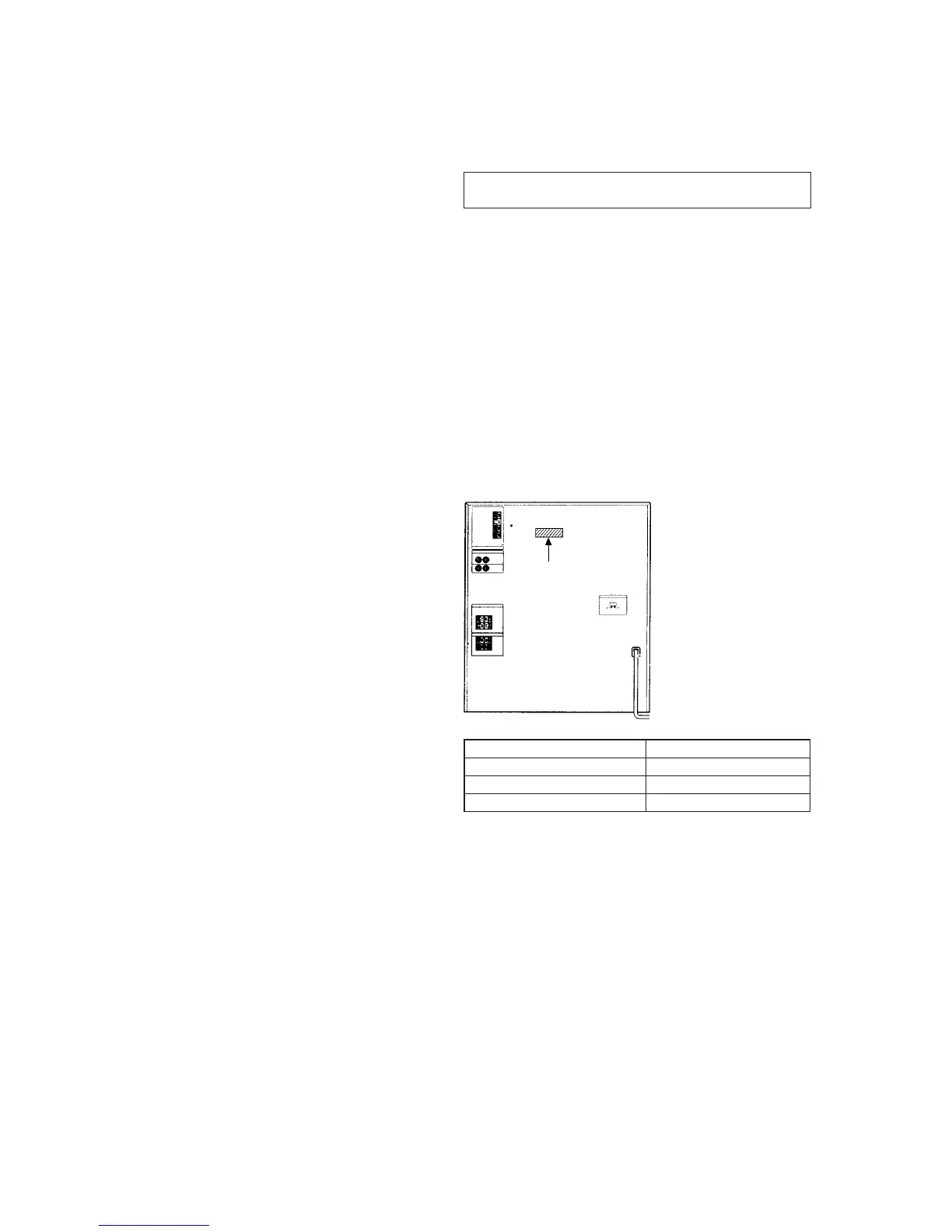
MODEL IDENTIFICATION
– BACK PANEL –
PARTS No.
MODEL PARTS No.
D590: US model 4-987-043-7π
D590: Canadian model 4-987-043-8π
XB4 4-987-927-0π