63
HVR-V1E/V1P
2-887-521-12(1)
L:\SONY\PV\CX91030\1130insatuPDF\2887521121_GB\2887521111HVRV1UVIN\01GB05BAS.
fm
Recording/Playback
* Change the settings according to the TV connected.
b Notes
• If you connect your camcorder to your TV using more than one type of cable to output images from a jack
other than the i.LINK jack, the order of priority of the output signals is as follows:
HDMI t component video t SVIDEO t audio/video.
• See page 128 for the details of i.LINK.
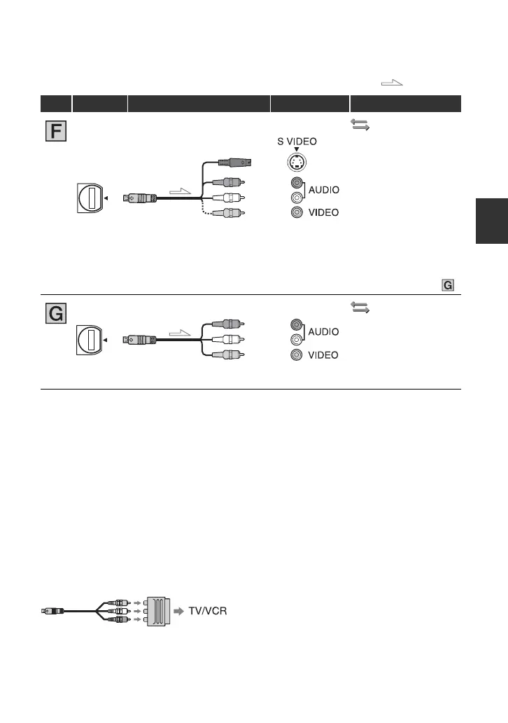
When connecting to your TV via a VCR
Select the connecting method on page 92 depending on the input jack of the VCR. Connect
your camcorder to the LINE IN input on the VCR using the A/V connecting cable. Set the
input selector on the VCR to LINE (VIDEO 1, VIDEO 2, etc.).
If your TV/VCR has a 21-pin adaptor (EUROCONNECTOR)
Use a 21-pin adaptor (optional) to view playback pictures.
(IN/OUT REC)
menu t
[VCR HDV/DV] t
[AUTO] (p. 82)
[DOWN CONVERT] t
[SQUEEZE]/[LETTER
BOX]/[EDGE CROP]*
(p. 84)
b Notes
• When connecting only an S VIDEO plug (S VIDEO channel), audio signals are not output. To output
audio signals, connect the white and red plugs of the A/V connecting cable with an S VIDEO cable to the
audio input jack of your TV.
• This connection produces higher resolution pictures compared with the A/V connecting cable (Type ).
(IN/OUT REC)
[VCR HDV/DV] t
[AUTO] (p. 82)
[DOWN CONVERT] t
[SQUEEZE]/[LETTER
BOX]/[EDGE CROP]*
(p. 84)
: Signal flow
Type Camcorder Cable TV Menu Setting
3
A/V connecting cable with
S VIDEO (optional)
(Red)
(White)
(Yellow)
3
A/V connecting cable
(supplied)
(Red)
(White)
(Yellow)