4
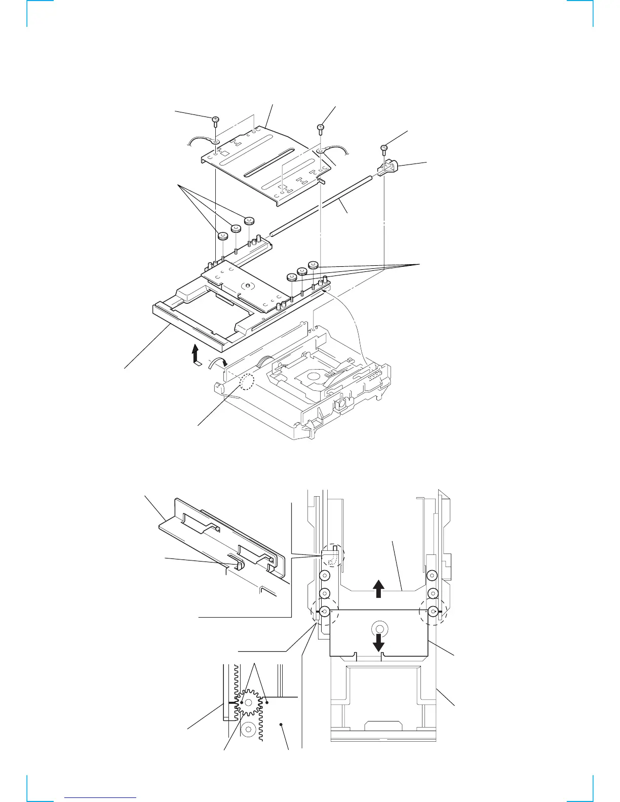
Bracket (top)
5
Three gears
(top)
5
Three gears (top)
9
Remove the tray asssembly
in the direction of the arrow
B
.
1
Rotate the pully gear in the direction
of the arrow
A
and pull the tray assembly.
3
Lug
8
Shaft
B
A
When the tray assembly is attached,
move the slider assembly in the direction
of the arrow
B
so that the pin is located
in the position as shown above.
Then attach the tray assembly.
Pin
Slider assembly
Slider assembly
Tray assembly
Slider (D) assembl
Slider (D) assembly
When the gears (top) (two gears on the front)
are attached, pull the tray assembly out in the
direction of the arrow
A
and align the rack (L)
and slider (D) assembly as shown.
Rack (L)
Gear (top)
Mark
NOTE FOR INSTALLATION
 Loading...