59
Pin No. Pin Name I/O Description
47 NC
O Not used (open)
48 CSET0
I Destination setting terminal (US, Canadian models: fixed at “L”, AEP, UK models: fixed at “H”)
49 CSET1
I Destination setting terminal (US, Canadian models: fixed at “H”, AEP, UK models: fixed at “L”)
50 730/930
I Setting terminal for the model (fixed at “H” in this set)
51 NC
I Not used (fixed at “H”)
52 MNT2 (XBUSY) I
Busy signal input from the CXD2656R (IC121)
53 DIG-RST O
Reset signal output to the CXD2656R (IC121) and BH6511FS (IC152) “L”: reset
54 MNT1 (SHOCK) I
Track jump detection signal input from the CXD2656R (IC121)
55 SENS
I Internal status (SENSE) input from the CXD2656R (IC121)
56 LDON O
Laser diode on/off control signal output to the automatic power control circuit “H”: laser on
57 REFLECT I
Detection input from the disc reflection rate detect switch (S102)
“L”: high reflection rate disc, “H”: low reflection rate disc
58 PROTECT I
Rec-proof claw detect input from the protect detect switch (S102) “H”: write protect
59 WR-PWR
O
Laser power select signal output to the CXD2656R (IC121) and HF module switch circuit
“L”: playback mode, “H”: recording mode
60 MNT3 (SLOCK) I
Spindle servo lock status monitor signal input from the CXD2656R (IC121)
61 SDA I/O
Two-way data bus with the EEPROM (IC171)
62 +3.3V
— Power supply terminal (+3.3V)
63
NC I Not used (fixed at “L”)
64 GND
— Ground terminal
65 SCTX O
Recording data output enable signal output to the CXD2656R (IC121) and overwrite head
driver (IC181) Writing data transmission timing output (Also serves as the magnetic head on/off
output)
66 SCL O
Clock signal output to the EEPROM (IC171)
67
MNT0 (FOK)
I
Focus OK signal input from the CXD2656R (IC121)
“H” is input when focus is on (“L”: NG)
68 LIMIT-IN
I
Detection input from the sled limit-in detect switch (S101)
The optical pick-up is inner position when “L”
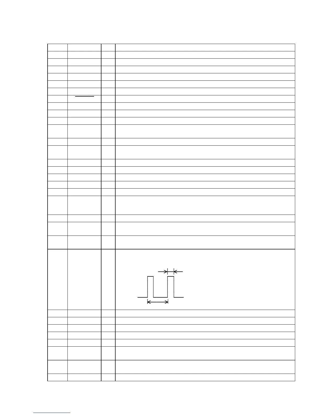
Laser modulation select signal output to the HF module switch circuit
Stop: “L”, Playback power: “H”,
Recording power:
69 MOD
O
70 XLATCH
O Serial data latch pulse signal output to the CXD2656R (IC121)
71 NC
I Not used (fixed at “L”)
72 REC/PB
I Not used (fixed at “L”)
73 PACK-IN I
Detection input from the disc detect switch Not used (fixed at “L”)
74 PB-P I
Detection input from the playback position detect switch (S604) “L” active
75 CHACK IN I
Detection input from the disc chucking-in detect switch “L”: chucking
Not used (fixed at “H”)
76 PACK-OUT I
Detection input from the loading-out detect switch (S602)
“L” at a load-out position, others: “H”
77 REC-P I
Detection input from the recording position detect switch (S601) “L” active
2 sec
0.5 sec
 Loading...