2-7
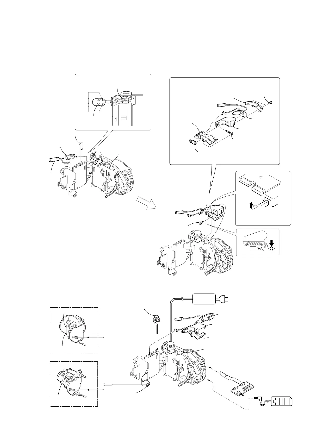
2-7. STROBOSCOPE SECTION (FLASH UNIT)
CD-
333
CD-
334
1 Precision screw
(DIA 1.7 × 4)
3 Stroboscope
base
1 ST sensor
lever
2 ST-POP-UP
spring
7 Flash unit
5 Stroboscope
case assembly
6 Stroboscope
cover
2 Remove the stroboscope
section in the direction
of the arrow A.
[FLASH UNIT SERVICE POSITION]
3 Discharging the capacitor
Capacitor
Capacitor cap
Short jig
Note: The charging capacitor is charged to the maximum of 300V.
There is a danger of electric shock due to the high voltage when the capacitor is touched by bare hand.
Discharge the voltage remained in the capacitor, referring to the Service Note (See page 5).
A
2 Capacitor
1 Capacitor cap
4 Sheet (UW)
4 Two precision
screws
(DIA 1.7 × 4)
CPC-9 jig
(J-6082-393-C)
1
18
Adjustment remote
commander (RM-95
AC IN
CD-334 board
CD-333 board
(CD300)
(CD200)
Lens block assembly
Lens block assembly
AC power
adaptor
Control switch block
(RL-503) (6P)
5 Control switch block
(ZK-503) (14P)
Flash unit
Stroboscope base, ST sensor lever,
ST-POP-UP spring
Stroboscope case assembly
FP-364 flexible
board (70P)
MD-
083
JK-
208
SY-
67
MD-
083
JK-
208
SY-
67
MD-
083
JK-
208
SY-
67
Control switch block
(ZK-503) (14P)

 Loading...


